Download

1 / 50
500 likes | 517 Views
Learn about transducers, dampers, and venturis for efficient use of pneumatic systems in FRC robotics. Discover alternative configurations, limitations, and expert tips to build and care for your system effectively.

E N D
FRC Pneumatics Nate Laverdure FRC Team 122
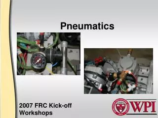
What is this presentation? Goals: • Teach you the words transducer, damper, and venturi • Attempt to: • Show that pneumatics have great advantages – if used correctly! • Provide a workable understanding of FRC pneumatics My personal goal: inspire you to build your own pneumatic system!
Alternative configurations Three major categories: • On-board compression • Off-board compression • Serious off-board compression
PS CMP TANK HP TANK MP LP
PS CMP TANK HP Off-board TANK MP LP
Off-board compression Why? • Less weight (about 5 lb) • Less power draw during the match
Off-board compression Why not? • No pressure regeneration during the match • No way to replace pressure lost to leaks • Adds an additional pre-match check
Off-board compression limitations Off-board compressor must be: • Powered by robot Power must come from Spike Relay on robot • Controlled by robot Via pressure switch Digital Sidecar cRIO • Protected by relief valve • Ventable Requires additional vent valve
PS CMP TANK HP Off-board TANK MP LP
PS CMP TANK HP Seriously off-board TANK MP LP
Serious off-board compression All the limitations of standard off-board compression, PLUS: • On-board storage is limited to only 60 psig
Building a pneumatic system General guidelines: • Read, know, and understand all the FRC pneumatics rules • Be able to explain your system to the inspectors
Building a pneumatic system General guidelines: • Read, know, and understand all the FRC pneumatics rules • Be able to explain your system to the inspectors Here’s a $6,000 hint: Refer to a printed flow diagram during inspection!
Building a pneumatic system Tips for tube fittings: • Use plastic push-to-connect fittings where possible (Less weight compared to brass fittings)
Building a pneumatic system Tips for tube fittings: • To connect: push tube in until firmly seated • To remove: press rim down, then pull tube out • Tubes cut at an angle will leak
Building a pneumatic system Tips for teflon tape: • Use 4 to 6 wraps of tape • Don’t use tape more than once • Wrap tape in the right direction • Don’t allow loose pieces of tape to get into the tubing
Building a pneumatic system Tips for brass fittings: • Brass is very soft • Do not over-torque • Do not use adjustable wrenches • Use box-end wrenches where possible
Caring for your pneumatics Problems maintaining pressure: Chronic leak Acute catastrophic pressure loss
Caring for your pneumatics Problems maintaining pressure: Chronic leak Acute catastrophic pressure loss Catastrophic pressure loss may be caused by: • Tube disconnection or breakage • Component failure
Caring for your pneumatics Tips for avoiding leaks: • Use as few fittings as possible • Perform leak test as each component is added • Use leak test fluid
Leak test fluid Recipe: • Add 2 tbsp dish soap to empty spray bottle • Fill spray bottle with water Directions: • Shake well • Cover all exposed electrical parts! • Spray directly on pressurized pneumatics
Caring for your pneumatics Protect your cylinders— • Thin wall tube can be crushed by side impacts • Internal seals will not handle side loads • Not repairable!
Design sequence • Find the required stroke length • Find the force & set the operating pressure • Guess how many times you will actuate the cylinder during a typical match • Find the required storage capacity
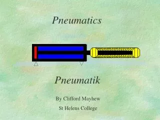
Determining the actuation force P1 P2 A
Determining the actuation force F1= P1A F2= P2A
Determining the actuation force F = F1 – F2= A(P1 – P2)
Determining the actuation force Warning: simplification! Because of piston rod, A1 ≠ A2 F = F1 – F2= A(P1 – P2)
Determining the actuation force P 0 F = F1 – F2= A(P1 – P2) F = PA
Example • Find the required stroke length • Find the force & set the operating pressure • Guess how many times you will actuate the cylinder during a typical match • Find the required storage capacity
Example Cylinder Stroke length L = 3 in L
Example • Find the required stroke length • Find the force & set the operating pressure • Guess how many times you will actuate the cylinder during a typical match • Find the required storage capacity
Example Cylinder Stroke length L = 3 in Diameter d = 1 in Area A = (d2)(π/4) = .785 in2 d L P
Example Cylinder Stroke length L = 3 in Diameter d = 1 in Area A = (d2)(π/4) = .785 in2 Pressure Puse = 60 psig = 60 lbf/in2 d L P
Example Cylinder Stroke length L = 3 in Diameter d = 1 in Area A = (d2)(π/4) = .785 in2 Pressure Puse = 60 psig = 60 lbf/in2 Force F = (Puse)(A) = 47 lbf d L P
Example • Find the required stroke length • Find the force & set the operating pressure • Guess how many times you will actuate the cylinder during a typical match • Find the required storage capacity
Example Cylinder # Actuations Nactuations = 10 + 10 = 20
Example Cylinder # Actuations Nactuations = 10 + 10 = 20 Warning: Remember to count both the forward and reverse strokes!
Example Cylinder # Actuations Nactuations = 10 + 10 = 20 Gas use = ~(Nactuations)(Puse)(Vcyl) = (20)(60 psig)(2.36 in3) = 2832 in*lbf
Example Cylinder # Actuations Nactuations = 10 + 10 = 20 Gas use = ~(Nactuations)(Puse)(Vcyl) = (20)(60 psig)(2.36 in3) = 2832 in*lbf This is in units of energy!
Example • Find the required stroke length • Find the force & set the operating pressure • Guess how many times you will actuate the cylinder during a typical match • Find the required storage capacity
Example Storage Volume Vtank = (L)(A) = 16 in3 Pressure Pstore = 120 psig # Tanks Ntanks = 2
Example Storage Volume Vtank = (L)(A) = 16 in3 Pressure Pstore = 120 psig # Tanks Ntanks = 2 Gas storage = ~(Ntanks)(Pstore)(Vtank) = (2)(120 psig)(16 in3) = 3840 in*lbf
Is the example design OK? Safety factor η = Gas storage 3840 in*lbf Gas use 2832 in*lbf = = 1.36 =
Is the example design OK? Safety factor η = Gas storage 3840 in*lbf Gas use 2832 in*lbf = = 1.36 = Result: The design is marginal. Add another tank, then test to make sure it works!
Gotchas Inspection checklist: • Relief valve is set at 125 psig • Off-board compressor must be controlled by cRIO • Vent valve must release all system pressure
Gotchas Inspection checklist: • Relief valve is set at 125 psig • Off-board compressor must be controlled by cRIO • Vent valve must release all system pressure Mitigations: • The KOP relief valve is not pre-calibrated! Set the relief valve per instructions.
Gotchas Inspection checklist: • Relief valve is set at 125 psig • Off-board compressor must be controlled by cRIO • Vent valve must release all system pressure Mitigations: • Build an off-board compression rig, complete with: • Compressor • Relief valve • Vent valve • Pressure gauge • Do not use shop air!
Gotchas Inspection checklist: • Relief valve is set at 125 psig • Off-board compressor must be controlled by cRIO • Vent valve must release all system pressure Mitigations: • Test all configurations • Can be caused by: • Solenoids with closed center positions • Systems that switch between pressures • Systems that stop cylinders partway through their stroke
FRC Pneumatics Nate Laverdure FRC Team 122