Download
1 / 74
750 likes | 778 Views
Explore the complexities of the network layer, including routing mechanisms, packet forwarding, and priorities. Learn about connection-oriented and connectionless services and challenges in addressing and routing information.

E N D
Chapter 7Packet-Switching Networks Network Services and Internal Network Operation Datagrams and Virtual Circuits Routing in Packet Networks Shortest Path Routing
Chapter 7Packet-Switching Networks Network Services and Internal Network Operation
Network Layer • Network Layer: the most complex layer • Requires the coordinated actions of multiple, geographically distributed network elements (switches & routers) • Must be able to deal with very large scales • Billions of users (people & communicating devices) • Biggest Challenges • Addressing: where should information be directed to? • Routing: what path should be used to get information there?
t1 t0 Network Packet Switching • Transfer of information as payload in data packets • Packets undergo random delays & possible loss • Different applications impose differing requirements on the transfer of information
Messages Messages Segments Transport layer Transport layer Network service Network service Network layer Network layer Network layer Network layer Data link layer Data link layer Data link layer Data link layer End system β End system α Physical layer Physical layer Physical layer Physical layer Network Service • Network layer can offer a variety of services to transport layer • Connection-oriented service or connectionless service • Best-effort or delay/loss guarantees
C 3 2 1 2 1 2 2 1 1 End system α End system β 1 1 1 2 2 2 3 3 3 2 4 1 4 2 2 2 1 2 1 2 1 1 1 3 Medium 2 1 B A Network 3 1 Physical layer entity Network layer entity 3 Network layer entity Data link layer entity 2 4 Transport layer entity Complexity at the Edge or in the Core?
Network Layer Functions Essential • Routing: mechanisms for determining the set of best paths for routing packets requires the collaboration of network elements • Forwarding: transfer of packets from NE inputs to outputs • Priority & Scheduling: determining order of packet transmission in each NE Optional: congestion control, segmentation & reassembly, security
Chapter 7Packet-Switching Networks Datagrams and Virtual Circuits
Backbone Network Switch Access Network The Switching Function • Dynamic interconnection of inputs to outputs • Enables dynamic sharing of transmission resource • Two fundamental approaches: • Connectionless • Connection-Oriented: Call setup control, Connection control
Packet switching network Transfers packets between users Transmission lines + packet switches (routers) Origin in message switching Two modes of operation: Connectionless Virtual Circuit User Transmission line Network Packet switch Packet Switching Network
Message Message Message Source Message Switches Destination Message Switching • Message switching invented for telegraphy • Entire messages multiplexed onto shared lines, stored & forwarded • Headers for source & destination addresses • Routing at message switches • Connectionless
Source T t Switch 1 t Switch 2 t t Destination Delay Minimum delay = 3 + 3T Message Switching Delay Additional queueing delays possible at each link
Approach 1: send 1 Mbit message Probability message arrives correctly On average it takes about 3 transmissions/hop Total # bits transmitted ≈ 6 Mbits source dest BER=p=10-6 BER=10-6 Long Messages vs. Packets 1 Mbit message How many bits need to be transmitted to deliver message? • Approach 2: send 10 100-kbit packets • Probability packet arrives correctly • On average it takes about 1.1 transmissions/hop • Total # bits transmitted ≈ 2.2 Mbits
Packet 1 Packet 1 Packet 2 Packet 2 Packet 2 Packet Switching - Datagram • Messages broken into smaller units (packets) • Source & destination addresses in packet header • Connectionless, packets routed independently (datagram) • Packet may arrive out of order • Pipelining of packets across network can reduce delay, increase throughput • Lower delay that message switching, suitable for interactive traffic
t 1 3 2 t 3 1 2 t 1 2 3 t Delay Packet Switching Delay Assume three packets corresponding to one message traverse same path Minimum Delay = 3τ + 5(T/3) (single path assumed) Additional queueing delays possible at each link Packet pipelining enables message to arrive sooner
Source t 1 3 2 Switch 1 t 3 1 2 Switch 2 t 1 2 3 t Destination L hops 3 hops L + (L-1)P first bit received 3 + 2(T/3) first bit received L + LP first bit released 3 + 3(T/3) first bit released 3 + 5 (T/3) last bit released L + LP + (k-1)P last bit released where T = k P Delay for k-Packet Message over L Hops
Route determined by table lookup Routing decision involves finding next hop in route to given destination Routing table has an entry for each destination specifying output port that leads to next hop Size of table becomes impractical for very large number of destinations Destination Output address port 0785 7 1345 12 1566 6 2458 12 Routing Tables in Datagram Networks
Example: Internet Routing • Internet protocol uses datagram packet switching across networks • Networks are treated as data links • Hosts have two-port IP address: • Network address + Host address • Routers do table lookup on network address • This reduces size of routing table • In addition, network addresses are assigned so that they can also be aggregated • Discussed as CIDR in Chapter 8
Packet Packet Packet Packet Virtual circuit Packet Switching – Virtual Circuit • Call set-up phase sets ups pointers in fixed path along network • All packets for a connection follow the same path • Abbreviated header identifies connection on each link • Packets queue for transmission • Variable bit rates possible, negotiated during call set-up • Delays variable, cannot be less than circuit switching
Connect request Connect request Connect request SW 1 SW n SW 2 … Connect confirm Connect confirm Connect confirm Connection Setup • Signaling messages propagate as route is selected • Signaling messages identify connection and setup tables in switches • Typically a connection is identified by a local tag, Virtual Circuit Identifier (VCI) • Each switch only needs to know how to relate an incoming tag in one input to an outgoing tag in the corresponding output • Once tables are setup, packets can flow along path
t Connect request 1 3 2 CC t Release 3 CR 1 2 CC t Connect confirm 1 2 CR 3 t Connection Setup Delay • Connection setup delay is incurred before any packet can be transferred • Delay is acceptable for sustained transfer of large number of packets • This delay may be unacceptably high if only a few packets are being transferred
Each input port of packet switch has a forwarding table Lookup entry for VCI of incoming packet Determine output port (next hop) and insert VCI for next link Very high speeds are possible Table can also include priority or other information about how packet should be treated Input VCI Output port Output VCI 12 44 13 15 15 23 16 27 13 58 7 34 Virtual Circuit Forwarding Tables
Source t 2 1 3 Switch 1 t 2 3 1 Switch 2 t 2 1 3 t Destination Minimum delay = 3 + T Cut-Through switching • Some networks perform error checking on header only, so packet can be forwarded as soon as header is received & processed • Delays reduced further with cut-through switching
Message vs. Packet Minimum Delay • Message: L t + L T = L t + (L – 1) T + T • Packet L t + L P + (k – 1) P = L t + (L – 1) P + T • Cut-Through Packet (Immediate forwarding after header) = L t + T Above neglect header processing delays
Example: ATM Networks • All information mapped into short fixed-length packets called cells • Connections set up across network • Virtual circuits established across networks • Tables setup at ATM switches • Several types of network services offered • Constant bit rate connections • Variable bit rate connections
Chapter 7Packet-Switching Networks Datagrams and Virtual Circuits Structure of a Packet Switch
• • • • • • • • • Packet Switch: Intersection where Traffic Flows Meet 1 1 2 2 N N • Inputs contain multiplexed flows from access muxs & other packet switches • Flows demultiplexed at input, routed and/or forwarded to output ports • Packets buffered, prioritized, and multiplexed on output lines
“Unfolded” View of Switch Ingress Line Cards Header processing Demultiplexing Routing in large switches Controller Routing in small switches Signalling & resource allocation Interconnection Fabric Transfer packets between line cards Egress Line Cards Scheduling & priority Multiplexing Controller 1 Line card 1 Line card 2 2 Line card Line card 3 3 Line card Interconnection fabric Line card … … … … N N Line card Line card Input ports Output ports Data path Control path (a) Generic Packet Switch
Folded View 1 circuit board is ingress/egress line card Transceiver Framer Network processor Backplane transceivers Framer Transceiver To other line cards To physical ports To switch fabric Interconnection fabric Line Cards • Physical layer processing • Data link layer processing • Network header processing • Physical layer across fabric + framing
Shared Memory Packet Switch Output Buffering Ingress Processing Connection Control 1 1 Queue Control 2 2 3 3 Shared Memory … … N N Small switches can be built by reading/writing into shared memory
Chapter 7Packet-Switching Networks Routing in Packet Networks
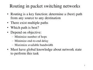
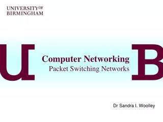
1 3 6 4 2 Node (switch or router) 5 Routing in Packet Networks • Three possible (loopfree) routes from 1 to 6: • 1-3-6, 1-4-5-6, 1-2-5-6 • Which is “best”? • Min delay? Min hop? Max bandwidth? Min cost? Max reliability?
Creating the Routing Tables • Need information on state of links • Link up/down; congested; delay or other metrics • Need to distribute link state information using a routing protocol • What information is exchanged? How often? • Exchange with neighbors; Broadcast or flood • Need to compute routes based on information • Single metric; multiple metrics • Single route; alternate routes
Routing Algorithm Requirements • Responsiveness to changes • Topology or bandwidth changes, congestion • Rapid convergence of routers to consistent set of routes • Freedom from persistent loops • Optimality • Resource utilization, path length • Robustness • Continues working under high load, congestion, faults, equipment failures, incorrect implementations • Simplicity • Efficient software implementation, reasonable processing load
2 7 1 8 B 1 3 3 A 6 5 1 5 4 2 VCI 4 Host Switch or router 3 5 2 5 C 6 D 2 Routing in Virtual-Circuit Packet Networks • Route determined during connection setup • Tables in switches implement forwarding that realizes selected route
Node 3 Incoming Outgoing Node 6 Node 1 Node VCI Node VCI 1 2 6 7 Incoming Outgoing Incoming Outgoing 1 3 4 4 Node VCI Node VCI Node VCI Node VCI 4 2 6 1 3 7 B 8 A 1 3 2 6 7 1 2 3 1 B 5 A 5 3 3 6 1 4 2 B 5 3 1 3 2 A 1 4 4 1 3 B 8 3 7 3 3 A 5 Node 4 Incoming Outgoing Node VCI Node VCI 2 3 3 2 Node 2 Node 5 3 4 5 5 Incoming Outgoing Incoming Outgoing 3 2 2 3 Node VCI Node VCI Node VCI Node VCI 5 5 3 4 C 6 4 3 4 5 D 2 4 3 C 6 D 2 4 5 Routing Tables in VC Packet Networks • Example: VCI from A to D • From A & VCI 5 → 3 & VCI 3 → 4 & VCI 4 • → 5 & VCI 5 → D & VCI 2
Node 3 Destination Next node Node 6 Node 1 1 1 Destination Next node Destination Next node 2 4 1 3 2 2 4 4 2 5 3 3 5 6 3 3 4 4 6 6 4 3 5 2 5 5 6 3 Node 4 Destination Next node 1 1 2 2 Node 2 Node 5 3 3 Destination Next node Destination Next node 5 5 1 1 1 4 6 3 3 1 2 2 4 4 3 4 5 5 4 4 6 5 6 6 Routing Tables in Datagram Packet Networks
0001 0100 1011 1110 0000 0111 1010 1101 1 4 3 R2 R1 5 2 0011 0101 1000 1111 0011 0110 1001 1100 0001 4 0100 4 1011 4 … … 0000 1 0111 1 1010 1 … … Non-Hierarchical Addresses and Routing • No relationship between addresses & routing proximity • Routing tables require 16 entries each
0100 0101 0110 0111 0000 0001 0010 0011 1 4 3 R2 R1 5 2 1100 1101 1110 1111 1000 1001 1010 1011 00 1 01 3 10 2 11 3 00 3 01 4 10 3 11 5 Hierarchical Addresses and Routing • Prefix indicates network where host is attached • Routing tables require 4 entries each
Specialized Routing • Flooding • Useful in starting up network • Useful in propagating information to all nodes • Deflection Routing • Fixed, preset routing procedure • No route synthesis
Flooding Send a packet to all nodes in a network • No routing tables available • Need to broadcast packet to all nodes (e.g. to propagate link state information) Approach • Send packet on all ports except one where it arrived • Exponential growth in packet transmissions
1 3 6 4 2 5 Flooding is initiated from Node 1: Hop 1 transmissions
1 3 6 4 2 5 Flooding is initiated from Node 1: Hop 2 transmissions
1 3 6 4 2 5 Flooding is initiated from Node 1: Hop 3 transmissions
Limited Flooding • Time-to-Live field in each packet limits number of hops to certain diameter • Each switch adds its ID before flooding; discards repeats • Source puts sequence number in each packet; switches records source address and sequence number and discards repeats
Chapter 7Packet-Switching Networks Shortest Path Routing
Shortest Paths & Routing • Many possible paths connect any given source and to any given destination • Routing involves the selection of the path to be used to accomplish a given transfer • Typically it is possible to attach a cost or distance to a link connecting two nodes • Routing can then be posed as a shortest path problem
Routing Metrics Means for measuring desirability of a path • Path Length = sum of costs or distances • Possible metrics • Hop count: rough measure of resources used • Reliability: link availability; BER • Delay: sum of delays along path; complex & dynamic • Bandwidth: “available capacity” in a path • Load: Link & router utilization along path • Cost: $$$
Shortest Path Approaches Distance Vector Protocols • Neighbors exchange list of distances to destinations • Best next-hop determined for each destination • Ford-Fulkerson (distributed) shortest path algorithm Link State Protocols • Link state information flooded to all routers • Routers have complete topology information • Shortest path (& hence next hop) calculated • Dijkstra (centralized) shortest path algorithm
Distance VectorDo you know the way to San Jose? San Jose 294 San Jose 392 San Jose 596 San Jose 250