Download
1 / 40
400 likes | 718 Views
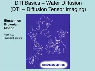
Diffusion Tensor Imaging MRI concept. Monil Shah Tuesday, July 18, 2006 Advisor: Prof. Andreas Linninger Laboratory for Product and Process Design , Department of Chemical Engineering, University of Illinois, Chicago, IL 60607, U.S.A. MRI.

E N D
Diffusion Tensor Imaging MRI concept Monil Shah Tuesday, July 18, 2006 Advisor: Prof. Andreas Linninger Laboratory for Product and Process Design, Department of Chemical Engineering, University of Illinois, Chicago, IL 60607, U.S.A.
MRI • Magnetic Resonance Imaging is an imaging modality which is primarily used to construct pictures of the NMR signal from the hydrogen atoms in an object (Fat, Water ).
Basics of MRI • Principle of Electromagnetic Induction Moving electric charge (i.e. electric current) produces magnetic field and vice versa
An MRI scanner magnetic field is usually created by producing an electrical current in a tube of superconducting material • Most clinical scanners are 1.5 Tesla • The stronger the magnetic field, the stronger the MRI signal.
Basics of MRI • Spin Physics • When placed in a magnetic field of strength B, a particle with a net spin can absorb a photon, of frequency .The frequency depends on the gyromagnetic ratio, of the particle. for hydrogen, = 42.58 MHz / T. • Protons have positive electric charge and "spin" which results in their behaving like little dipole magnets. • When a group of spins is placed in a magnetic field, each spin aligns in one of the two possible orientations.
Boltzmann’s Statistics • At room temperature, the number of spins in the lower energy level, N+, slightly outnumbers the number in the upper level, N-. Boltzmann statistics tells us that N-/N+ = e-E/kT. • E is the energy difference between the spin states • k is Boltzmann's constant, 1.3805x10⁻²³ J/Kelvin • and T is the temperature in Kelvin. • But only slightly more than 1/2 of the protons will actually line up, the others will be in the opposite orientation. The stronger the field, the more will line up.
Pulsed magnetic Fields • A coil of wire placed around the X axis will provide a magnetic field along the X axis when a direct current is passed through the coil. An alternating current will produce a magnetic field which alternates in direction. • When the alternating current through the coil is turned on and off, it creates a pulsed B1 magnetic field along the X' axis.
Relaxation • T1 Relaxation: • The time constant which describes how MZ returns to its equilibrium value is called the spin lattice relaxation time (T1). The equation governing this behavior as a function of the time t after its displacement is: Mz = Mo ( 1 - e-t/T1 )
Relaxation • T2 Relaxation: • In addition to the rotation, the net magnetization starts to dephase because each of the spin packets making it up is experiencing a slightly different magnetic field and rotates at its own Larmor frequency. • The time constant which describes the return to equilibrium of the transverse magnetization, MXY, is called the spin-spin relaxation time, T2. MXY =MXYo e-t/T2
Free Induction Decay • As transverse magnetization rotates about the Z axis, it will induce a current in a coil of wire located around the X axis. • Plotting current as a function of time gives a sine wave. • This wave will of course decay with time constant T2* due to dephasing of the spin packets. This signal is called a free induction decay (FID).
Basic Pulse Sequence • Spin Echo: • Here a 90 deg pulse is first applied to the spin system. • At some point in time after the 90o pulse, a 180o pulse is applied. This pulse rotates the magnetization by 180o about the X' axis. • The 180 deg pulse causes the magnetization to at least partially rephase and to produce a signal called an echo.
Gradients • If each of the regions of spin was to experience a unique magnetic field we would be able to image their positions. • A gradient in the magnetic field is what will allow us to accomplish this. A magnetic field gradient is a variation in the magnetic field with respect to position. • 3 Gradients applied: • Frequency encoding Gradient • Phase encoding Gradient • Slice selective Gradient
Diffusion Imaging • In the presence of B1, water molecules will cause phase dispersion of the transverse magnetization and hence, signal loss. The attenuation degree depends on: • – The structure of the tissue. • – Physical and physiological state of the tissue. • – Microenvironment. How to capture diffusion? • Motion Sensitizing Gradients • Diffusion Weighting Gradients
Diffusion Weighting Gradients • Increase the sensitivity of MRI signal to molecular diffusion. • The degree of attenuation is proportional with: – Diffusion Coefficient, D (mm2/s) – b-value (s/mm2) • Consists of two lobes with equal areas, • maximum amplitude allowed, and a longer pulse width than most of the imaging gradients • Random moving spins will accumulate different phases, and because of their random motion, phases will cancel out and hence signal loss will occur. • • The resultant MRI signal S is related to the variance of a Gaussian phase distribution, Φ2: S = S0 exp(-<Φ2>) = S0 exp(-bD) Where: • – S0 is the signal intensity in the absence of diffusion.
b-value b-values depends on: • » Gradient shape & amplitude • » Separation of the lobes • » Pulse width
Pulse sequence for Diffusion Imaging Most commonly used due to: – High acquisition speed (less than 100 ms/image) – High motion insensitivity
Generally, the restrictions on water diffusion imposed by macromolecules and tissue structures do not have sphearical symmetrty. • Restriction in one direction can be greater than that in other directions. • This causes Diffusion Anistropy • (Diffusion varies with spatial orientation.) • Mathematically directional dependence is expressed as a second rank tensor
Diffusion Tensor • The main axis of ellipsoid gives the main diffusion direction • Eccentricity of the ellipsoid provides information about degree of anistropy and its symmetry • Length of ellipsoid gives diffusion distance in that direction.