Download
1 / 56
610 likes | 926 Views
DCT. By : Naghmeh Karimi The material in this class presentation have been collected from different published works of other authors and are presented here for educational purposes only. Under supervision of: Dr. Fakhraie University of Tehran. Outline. Introduction JPEG coding

E N D
DCT By:Naghmeh Karimi The material in this class presentation have been collected from different published works of other authors and are presented here for educational purposes only. Under supervision of: Dr. Fakhraie University of Tehran Naghmeh Karimi; Tehran University
Outline • Introduction • JPEG coding • DCT technique Naghmeh Karimi; Tehran University
Introduction Naghmeh Karimi; Tehran University
JPEG Coding • Lossy • Lossless Naghmeh Karimi; Tehran University
Lossless Compression Compressed image data Source image data Predictor Entropy Coder Entropy_Table Specifications Naghmeh Karimi; Tehran University
Lossy Compression • Baseline sequential mode compression • Progressive mode • Hierarchical mode Naghmeh Karimi; Tehran University
Baseline Sequential mode • An image is partitioned into some 8 by 8 non-overlapping pixel blocks from left to right and top to bottom. • Each block is coded individually. Naghmeh Karimi; Tehran University
Progressive mode • Start with a low quality image and successively improve. • Spectral selection: Send DC component and first few AC coefficients first, then gradually some more ACs. 2. Successive approximation: send DCT coefficients MSB (most significant bit) to LSB (least significant bit). Naghmeh Karimi; Tehran University
Hierarchical mode • Down-sample by factors of 2 in each dimension, e.g., reduce 640 x 480 to 320 x 240 2. Code smaller image using another JPEG mode (Progressive, Sequential, or Lossless) 3. Decode and up-sample encoded image 4. Encode difference between the up-sampled and the original using Progressive,Sequential, or Lossless. Naghmeh Karimi; Tehran University
Hierarchical mode • An image is coded as a sequence of layers in a pyramid. • Except for the top level of pyramid, for each luminance and color component at the lower levels, the difference between the source components and the reference reconstructed image is coded. Naghmeh Karimi; Tehran University
Entropy table Entropy table Qtable Down sampling Baseline JPEG Encoder(block diagram) AC VLC Zigzag Compressed image data Q Zero shift DCT VLC Diff DC image Naghmeh Karimi; Tehran University
Color Transformation • The human visual systems is most sensitive to changes in luminance and less to changes in chrominance. • RGB must be converted to the other color systems . Naghmeh Karimi; Tehran University
YUV system • Y = 0.299R + 0.587G + 0.114B ; • U = B - Y ; • V = R - Y ; Naghmeh Karimi; Tehran University
Zero Shift • After transformation Y, U and V are in the range of [0,255] • Zero shift changes this range to [-128,127] Naghmeh Karimi; Tehran University
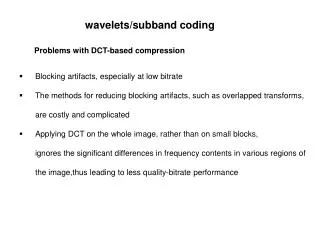
DCT • The strength of transform coding in achieving data compression is that the image energy of the most natural scenes is mainly concentrated in the low frequency region and hence into a few transform coefficients. Naghmeh Karimi; Tehran University
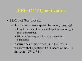
Quantization • Quantization allows us to reduce the accuracy with witch the DCT coefficients are represented when converting the DCT to an integer representation. • It tends to make many coefficients zero, specially those for high spatial frequencies. • Two standard table are available for quantization. Naghmeh Karimi; Tehran University
Zigzag Scan • The zigzag pattern used in the JPEG algorithms orders the basis functions from low to high spatial frequencies . • It facilitate entropy coding by encountering the most likely non-zero coefficient first. Naghmeh Karimi; Tehran University
Run Length Coding • For the JPEG standard, a symbol is structured in 2 parts: • Symbol1 (VLC) • Symbol2 binary representation of amplitude Naghmeh Karimi; Tehran University
Coding DC Coefficients • The differential rules are categorized based on the magnitude range called “CAT”. • The “CAT” is Variable Length Coded. Naghmeh Karimi; Tehran University
Coding AC Coefficients • For each non-zero AC coefficient in zigzag Scan symbol1 is described as a 2dimentional event of ( Run, Cat ). • Cat : category for the amplitude of a non-zero coefficient. • Run: the number of zeros preceding this non-zero coefficient. Naghmeh Karimi; Tehran University
Coding AC Coefficients(Cont.) • If Run is greater than 15 then (Run, Cat) must be broken to some (15,0) followed by a (Cat1, Run1). • Example: (34,5) (15,0),(15,0),(2,5) • The end of the block is represented by (0,0) Naghmeh Karimi; Tehran University
Improving DCT Efficiency • Using LUTs . • Using FDCT Algorithms. • Using Pipeline structures. Naghmeh Karimi; Tehran University
Example A= 5 (3,3) 111111110101101 Naghmeh Karimi; Tehran University
2-DCT Naghmeh Karimi; Tehran University
First_Technique • 8-point DCT and IDCT • DCT • Input :8 bit • Output:10 bit • IDCT • Input :10 bit • Output:8 bit Naghmeh Karimi; Tehran University
8-point IDCT Naghmeh Karimi; Tehran University
8-point IDCT(Cont.) Naghmeh Karimi; Tehran University
Rotator Naghmeh Karimi; Tehran University
Rotator • Another Architecture with 3 adder and 3 multiplier is possible. Naghmeh Karimi; Tehran University
8-point DCT Naghmeh Karimi; Tehran University
Rotator Naghmeh Karimi; Tehran University
Implementation Results Naghmeh Karimi; Tehran University
Second_Technique Naghmeh Karimi; Tehran University
1-D IDCT Equation Coefficients Original Coefficients Simplified Coefficients Naghmeh Karimi; Tehran University
Second_Technique Naghmeh Karimi; Tehran University
Total_Implementation Naghmeh Karimi; Tehran University
Wave-Forms Naghmeh Karimi; Tehran University
Results Naghmeh Karimi; Tehran University
Third_Technique(Pipeline) Naghmeh Karimi; Tehran University
Pipeline stages Naghmeh Karimi; Tehran University
Pipeline Structure • Each 1-D DCT stage : 8 clk cycle • 1-D DCT architecture latency : 48 clk cycle • The transpose buffer latency : 64 clk cycle • Total:160 clk cycle Naghmeh Karimi; Tehran University
Fourth_Technique Naghmeh Karimi; Tehran University
FDCT (cosine-factors) Naghmeh Karimi; Tehran University
Data flow graph for 8 point FDCT Naghmeh Karimi; Tehran University
Schematic of 2-D DCT Naghmeh Karimi; Tehran University
Schematic of transposition memory Naghmeh Karimi; Tehran University
Architecture and Operation of2-D DCT Circuit Reset Dout Din Clk Naghmeh Karimi; Tehran University
Timing Diagram for External In/Out Port (A): Serial to Parallel conversion for input (B):1-D DCT operation (C): Parallel to Serial conversion for output Naghmeh Karimi; Tehran University
Functionality of internally generated control signals Naghmeh Karimi; Tehran University
Row 1-D DCT Operation Timing Diagram of Row 1-D DCT Naghmeh Karimi; Tehran University