Download

1 / 29
290 likes | 438 Views
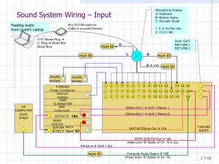
Wiring the new control system. MVRT 2010 – 2011 Season. Basic Wiring Principles. Color convention for insulation (according to rules) Power = red, white, brown Ground = black, brown Use right size (gauge/diameter) cables Big wire = smaller gauge = more current Basic types

E N D
Wiring the new control system MVRT 2010 – 2011 Season
Basic Wiring Principles • Color convention for insulation (according to rules) • Power = red, white, brown • Ground = black, brown • Use right size (gauge/diameter) cables • Big wire = smaller gauge = more current • Basic types • Solid – single wire • Stranded – multiple smaller wires twisted together • Jacketed – multiple insulated wires with an outer cover
Robot Battery • 12V Lead-Acid Battery • Connects to power block and main circuit breaker • Powers all functions of robot
Wiring diagram Battery
Main Circuit Breaker • Turns robot on and off • To turn it off press the red button on the top • To turn it on close the switch • Connects the battery to the power distribution board • Normally use the red power cable from the battery to the breaker
Wiring diagram Battery Circuit breaker
Power Distributor Board • Distributes power to all the electrical components • Makes sure not too much current is drawn and everything is well connected • Connects to everything that requires power
Wiring diagram Battery Circuit breaker Power distribution board
Compact RIO Controller (cRio) • Brains of Robot • Gets power from the power distributor board • Sends power and signal to the Digital Sidecard and the Wi-Fi interface • Connects via Wi-Fi to the driver station and the robot
Modules and Bumpers • Analog Input Module • Analog inputs with 3 pin connectors • Digital Adapter Module • Connects to Digital Sidecar with a ribbon cable • PWMs, Digital I/O, 3-pin relay connectors • Relay Module (On/Off) • Control solenoids (electrical controller used with pneumatic system)
Wiring diagram Battery cRio controller Digital module Solen- -oid module Analog module Circuit breaker Power distribution board
Digital Sidecar • Used to connect variety of different signals, mainly to the Victors • Connects to the cRio module and power distributor block
Wiring diagram Battery cRio controller Digital module Solen- -oid module Analog module Circuit breaker Digital sidecar Power distribution board
Jaguar Speed Controller • Determines how much power goes to the motor • Gets power from the distribution board, input from the digital sidecard, and outputs to the motors
Motors • Motors wired to Jaguar speed controller • Wired up by both the ground and the power • Wire with Powerpole connectors • Jaguars make motors move at a certain speed • Motors allow an object to rotate
Spike • Input: a voltage input • Output: voltage to a motor • Full forward (+12V) • Full backward (-12V) • Turns compressor on and off to charge pneumatics system • Wired to compressor and digital sidecar
Wiring diagram Battery cRio controller Digital module Solen- -oid module Analog module Circuit breaker Digital sidecar Power distribution board Digital sensors Motor speed controllers Spike relays motors compressor
Linksys Wi-Fi Interface • Connects the cRio to the driver station/router • Connected to the OI and the power distribution board
Wiring diagram Battery cRio controller Wireless bridge Digital module Solen- -oid module Analog module Circuit breaker Digital sidecar Power distribution board Pneumatic solenoid Analog sensors Digital sensors Motor speed controllers Spike relays motors compressor
WAGO & Sauro Connector • 2 pole • Uses – Power distributor to… • bumpers • gaming adapter • Digital side card Sauro Connector • 4 pole • Uses – Power distributor to… • cRio
Other parts/tools used to wire the robot • Servos • Electrical tape • PWM Wires • Zipties • Label Makers
Servos • Rotates from 0 to 254 • Once given position, stays there and cannot be moved unless “told” by the code • A very small motor
Servo 2011 • 2011 changes - Can use more servos starting this year • Max power = (0.5 * stall torque) * (0.5 * no load speed) • Load speed has to be less than 4W • Example (Hitec Hs – 322 servo) • Servo max power rating = torque x speed x unit conversion factor • Torque = 3/7 kg/cm = 0.36 NM • RPM = 0.15s @ 60 = 66.7 RPM • 0.36 NM x 66.7 RPM x 0.1047 = 2.5W
Electrical Tape • Prevents the electrical current from hurting people on battery terminals or open wire • Primarily used to insulate bare wires or ends • use red electrical tape for power wires • Use black tape for ground wires • Use to cover jaguar terminals
PWM • Stands for pulse width modulator • Used to transmit data to speed controllers • Red - power • Black - ground • White/Yellow - signal
Zip ties • Used to keep wiring neat and out of the way from moving parts to avoid the wires from getting cut
Label Maker • Labeling wire makes it easy to identify where it’s from / going to • Ex. label pwm cables from digital sidecar to jaguars