Download
1 / 63
700 likes | 887 Views
Learn to recognize, interpret, and use construction drawing terms, components, and symbols. Understand different types of construction drawings and their layout. Explore architectural and working drawings used for construction projects.

E N D
Introduction to Construction Drawings Module 00105-09
Objectives Upon completion of this module, you will be able to: 1. Recognize and identify basic construction drawing terms, components, and symbols. 2. Relate information on construction drawings to actual locations on the print. 3. Recognize different classifications of construction drawings. 4. Interpret and use drawing dimensions.
Performance Tasks • 1. Using the floor plan supplied with this module: • Locate the wall common to both interview rooms. • Determine the overall width of the structure studio. • Find the distance from the outside east wall to the center of the beam in the structure studio. • Find the elevation of the slab.
Construction drawings are architectural or working drawings used to represent a structure or system. • They are traditionally called blueprints because the lines on drawings were white on a blue background • Today most are created by CAD – computer-aided drafting – blue or black lines on a white background • A set of construction drawings almost always includes six major types of drawings – see next slide
Most drawings are laid out in a similar format. There are usually five parts to a construction drawing • Title Block • Border • Drawing area • Revision block • Legend
Title block • Normally in the lower right hand corner or across the right edge of the paper • Most title blocks include – Company logo • Sheet title – identifies the project • Date – date the drawing was checked and issued for construction • Drawn by – who drafted the drawing • Drawing number – code assigned to the project • Scale – ratio of the size of the object • Revision block – info on revisions
Border – Drawing area • Border - A clear area about half an inch around the edge of the drawing. Mainly there so that the drawing can be reproduced on printing machines and no information is lost • Drawing area – shows the information for constructing the project – floor plan, elevations of the building, sections, and details
Revision block - Legend • Revision block – usually located in the lower right corner inside or near the title block – in the drawing area • Used to record any changes in the drawings – contains a revision number, a brief description, the date, and the initials of the person who made the revisions • Legend – each line on a drawing has a specific design and thickness that identifies it – the identification of these lines and other symbols is called the legend – they are usually specific to the set of drawings in which they are contained
Civil Plans • Are used for work that has to do with construction in or on the earth • May be called site plans, survey plans, or plot plans • Show the location of the building on the site from an aerial view • Show the natural contour of the earth represented by contour lines • May include a landscape plan that shows trees, walks, driveways, utilities, the dimensions of the property
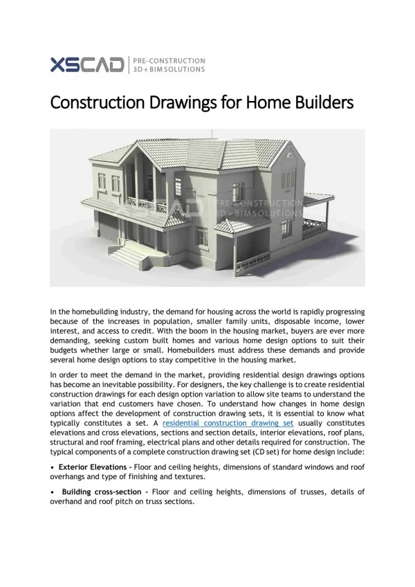
Architectural Plans • Show the design of the project • Floor plan – plan view – aerial view of the layout of each room – provides the most info about the project – show exterior and interior walls, doors, stairways, and mechanical equipment • Roof plan – a view of the roof from above the building – shows the shape of the roof and the materials used to finish it
Architectural drawings • Elevation drawings – side views – are called elevation because they show height – there are standard names for each elevation – example the side that faces south would be called the south elevation – they show the size of the building, style of the building and placement of doors, windows, chimneys, and decorative trim • Section drawings – shows how the structure is to be built – cross-sectional views that show the inside of the building – they show what materials to use and how the parts are to be put together
Architectural drawings • Detail drawings – enlarged views of some special features of a building, like floors and walls – enlarged to make details clearer • Architectural plans show the finish schedules to be used for the doors and windows – finish schedules for windows and doors tell the sizes and other information about the types of windows and doors to be used – finish schedules may also tell hardware and fixtures
Structural Plans • Set of engineered plans to support the architectural design – first part is the notes that give details of the materials to be used and the requirements to be followed • Foundation plan – shows the lowest level of the building(concrete footings, slabs, and foundation walls) – may show in detail how the foundation is to be reinforced • Structural plan also shows the materials that are to be used for the walls as well as the roof-framing plan
Mechanical Plans • Engineered plans for motors, pumps, piping systems, and piping equipment – tells what the contractor is to provide as well the location of grills and registers • Piping and instrumentation drawings are schematic diagrams of a complete piping system –they are not drawn to scale • Some jobs have a HVAC plan to tell the layout of the HVAC system
Figure 20 – Mechanical detail drawing for hot water riser and drain connections
Plumbing/Piping plans • Engineered plans that show the layout for the plumbing system that supplies hot and cold water, for the sewage disposal system, and for the location of plumbing fixtures • Some have a plumbing isometric drawing (3-D type drawing) to show the plumbing system
Figure 22 – Plumbing isometric drawing (sanitary riser diagram).
Electrical Plan • Engineered drawings for electrical supply and distribution • They may appear on the floor plan itself • They show locations of the meter, distribution panel, switchgear, convenience outlets, and special outlets • Usually start out with a set of general notes telling about transformers and underground penetrations to the building • May include location of lights and receptacles
Specifications & RFI • Specifications are statements that are provided to the general contractors defining the quality of work to be done and the materials to be used • Request for Information – RFI – a form to fill out if there is a discrepancy in the plans – worker – foreman-superintendent-general contractor-architect/engineer
Lines of construction • The lines commonly used on drawings are called the alphabet lines • Dimension lines – establish the sizes of parts if a structure – may end in arrows, dots, or slashes at a termination line drawn perpendicular to the dimension line • Leaders and arrowheads – identify the location of a specific part of the drawing – used with words, abbreviations, symbols, or keynotes • Property lines – show land boundaries
Lines of Construction • Cut lines – lines around part of a drawing that is to be shown in a separate cross-sectional view • Section cuts – shows areas not included in the cutting line view • Break lines – show where an object has been broken off to save space on the drawing • Hidden lines – identify part of a structure that is not visible on the drawing – may be drawn somewhere else • Centerlines – show the measured center of an object • Object lines – identify the object of primary interest or the closest object