Download
1 / 17
200 likes | 503 Views
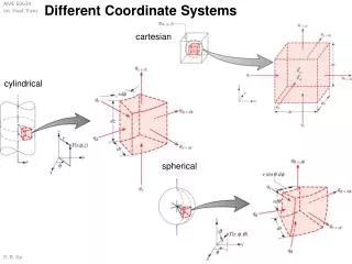
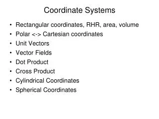
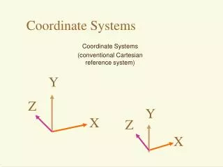
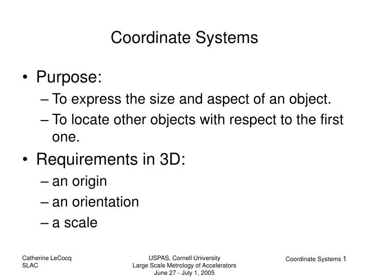
Purpose: To express the size and aspect of an object. To locate other objects with respect to the first one. Requirements in 3D: an origin an orientation a scale. Coordinate Systems. Magnet Accelerator Earth. Examples of Coordinate Systems.

E N D
Purpose: To express the size and aspect of an object. To locate other objects with respect to the first one. Requirements in 3D: an origin an orientation a scale Coordinate Systems USPAS, Cornell University Large Scale Metrology of Accelerators June 27 - July 1, 2005
Magnet Accelerator Earth Examples of Coordinate Systems USPAS, Cornell University Large Scale Metrology of Accelerators June 27 - July 1, 2005
Fiducialization Procedures for the ALS RingMagnets and the Booster Synchrotron GirdersJack Tanabe, Roderich Keller and Ted LauritzenLawrence Berkeley Laboratory, Berkeley, CA 94720, U. S. A.presented at IWAA90 The mechanical coordinate system of each magnet is defined with respect to the mechanical features of the core. The cores for each magnet are made from precision stamped laminations and the upper surfaces of assembled magnets and parting planes of two and three piece magnets are precisely parallel to the central axis of the magnet. Moreover, great care is taken in assembling the core segments so that the axes of each core segment are precisely normal to the planes of the laminations. Thus, the u/w plane (defining u’ and w’, the pitch and roll) of the magnet is determined from the upper plane of the assembled core or the parting plane of a core segment. USPAS, Cornell University Large Scale Metrology of Accelerators June 27 - July 1, 2005
There are five coordinate systems commonly used in the PEP-II Interaction Region. PEP-II Coordinate System Origin: Center of the PEP-II rings. Elevation above mean sea level = 65.986 m +X: Direction from the PEP-II ring center through the center of IR-12 (nominally north). +Y: Up, parallel to gravity vector through the ring center. +Z: Direction from the PEP-II ring center through the symmetry point (mid-arc) in Arc 3 (nominally east). PEP Control Line IR Reference Frame Collision Axis Coordinate System Detector Coordinate System PEPII Coordinate Systems USPAS, Cornell University Large Scale Metrology of Accelerators June 27 - July 1, 2005
PEPII Coordinate Systems USPAS, Cornell University Large Scale Metrology of Accelerators June 27 - July 1, 2005
Origin: Center of Mass Point at the surface Orientation: Axis of rotation Vertical Earth Coordinate Systems USPAS, Cornell University Large Scale Metrology of Accelerators June 27 - July 1, 2005
plumb line z P level surfaces W = const. g y Φ Λ x Vertical and Axis of Rotation USPAS, Cornell University Large Scale Metrology of Accelerators June 27 - July 1, 2005
z P h p φ λ 0 x Geocentric Systems y The principal radii of curvature: in the plane of the meridian: M in the plane of the prime vertical: N USPAS, Cornell University Large Scale Metrology of Accelerators June 27 - July 1, 2005
Today the center of mass and the axis of rotation of the Earth are well observed. The IERS was established as the International Earth Rotation Service in 1987 by the International Astronomical Union and the International Union of Geodesy and Geophysics and it began operation on 1 January 1988. In 2003 it was renamed to International Earth Rotation and Reference Systems Service. The primary objectives of the IERS are to serve the astronomical, geodetic and geophysical communities by providing the following: The International Celestial Reference System (ICRS) and its realization, the International Celestial Reference Frame (ICRF). The International Terrestrial Reference System (ITRS) and its realization, the International Terrestrial Reference Frame (ITRF). Earth orientation parameters required to study earth orientation variations and to transform between the ICRF and the ITRF. Geophysical data to interpret time/space variations in the ICRF, ITRF or earth orientation parameters, and model such variations. Standards, constants and models (i.e., conventions) encouraging international adherence. Before only local astronomical observations were possible and the common method was to decide that the geodetic and the astronomical latitude and longitude were set at one point. For the US, this was Meades Ranch in Kansas. So there were a wide variety of origin, orientation and ellipsoidal parameters. How to realize such CS? USPAS, Cornell University Large Scale Metrology of Accelerators June 27 - July 1, 2005
Before satellite geodesy In the USA: Clarke 1866 a = 6378206.4 m b = 6356584 m f-1 = 294.9786982 In France: Clarke 1880 a = 6378249 m b = 6356515 m World: Hayford 1909/1924 a = 6378388 m f-1 = 297.0 b = 6356912 m Now: GRS80 (Geodetic Reference System of 1980) a = 6378137 m b = 6356752.3141 m f-1 = 298.25722101 Ellipsoids USPAS, Cornell University Large Scale Metrology of Accelerators June 27 - July 1, 2005
The ITRS definition fulfills the following conditions: 1. It is geocentric, the center of mass being defined for the whole earth, including oceans and atmosphere. 2. The unit of length is the metre (SI). This scale is consistent with the TCG time coordinate for a geocentric local frame, in agreement with IAU and IUGG (1991) resolutions. This is obtained by appropriate relativistic modelling. 3. Its orientation was initially given by the BIH orientation at 1984.0. 4. The time evolution of the orientation is ensured by using a no-net-rotation condition with regards to horizontal tectonic motions over the whole earth. The ITRS is realized by estimates of the coordinates and velocities of a set of stations observed by VLBI, LLR, GPS, SLR, and DORIS. Its name is International Terrestrial Reference Frame. The ITRS can be connected to the International Celestial Reference System (ICRS) by use of the IERS Earth Orientation Parameters (EOP). Reference: http://tai.bipm.org/iers/conv2003/conv2003.html International Terrestrial Reference System http://www.iers.org/iers/earth/itrs/ USPAS, Cornell University Large Scale Metrology of Accelerators June 27 - July 1, 2005
= X3 X03 pole Greenwich earth’s rotation axis ecliptic geocenter equator Θ0 vernal equinox X1 X01 Transformation between CRF and TRFH-W and all, pages 25, 30-34 where USPAS, Cornell University Large Scale Metrology of Accelerators June 27 - July 1, 2005
X03(t0) X03(t) mean equator (t) mean equator (to) Eo 90º - ζ X01(to) E 90º + z X02(t0) X01(t) PrecessionH-W and all, page 31-32 USPAS, Cornell University Large Scale Metrology of Accelerators June 27 - July 1, 2005
ecliptic ε mean equator E Δψ Δε Et true equator NutationH-W and all, pages 32-33 USPAS, Cornell University Large Scale Metrology of Accelerators June 27 - July 1, 2005
CIO y xp mean Greenwich meridian yp CEP Rotation and Polar MotionH-W and all, pages 33-34 USPAS, Cornell University Large Scale Metrology of Accelerators June 27 - July 1, 2005
NAD83 is the North American Datum of 1983. It is the horizontal control datum for the United States, Canada, Mexico, and Central America, based on a geocentric origin and the Geodetic Reference System 1980. It is based on the adjustment of 250,000 points including 600 satellite Doppler stations which constrain the system to a geocentric origin. http://www.ngs.noaa.gov/faq.shtml#WhatDatum WGS84 is the World Geodetic System of 1984. It is the reference frame used by the U.S. Department of Defense (DoD) and is defined by the National Imagery and Mapping Agency (NIMA formerly the Defense Mapping Agency). WGS 84 was defined in January 1987 using Doppler satellite surveying techniques. It was used as the reference frame for broadcast GPS ephemerides beginning January 23, 1987. At 0000 GMT January 2, 1994, WGS 84 was upgraded in accuracy using GPS measurements. The formal name then became WGS 84 (G730) since the upgrade date coincided with the start of GPS Week 730. It became the reference frame for broadcast orbits on June 28, 1994. At 0000 GMT September 30, 1996 (the start of GPS Week 873), WGS 84 was redefined again and was more closely aligned with International Earth Rotation Service (IERS) Terrestrial Reference Frame (ITRF) 94. It is now formally called WGS 84 (G873). WGS 84 (G873) was adopted as the reference frame for broadcast orbits on January 29, 1997. Other Geocentric Systems USPAS, Cornell University Large Scale Metrology of Accelerators June 27 - July 1, 2005
Plane Coordinateshttp://gge.unb.ca/Research/GeodesyGroup/tutorial/tutorial.htm USPAS, Cornell University Large Scale Metrology of Accelerators June 27 - July 1, 2005