Download
1 / 69
700 likes | 1.07k Views
Illumination. outer cone. Inner cone. Point Light (Emit in all directions). Spot Light (Emit within a cone). Light Sources. Directional Light (Infinitely far away). Radial Intensity Attenuation.

E N D
outer cone Inner cone Point Light (Emit in all directions) Spot Light (Emit within a cone) Light Sources Directional Light (Infinitely far away)
Radial Intensity Attenuation The amplitude of a radiant energy at the distance dl is attenuated by the factor 1/dl2. For realistic effects: 1/ (a0+a1dl+a2dl2) local fl,radatten(dl)= 1.0 infinity
Directional Light Sources 00 < q ≤ 900 Object is within the spot light if cos a ≥ cos ql Vobj . Vlight = cos a Vobj Vlight a ql
Angular Intensity Attenuation Vobj fangatten(a) = cosa a 1.0 if light source is not spotlight fl,angatten = 0.0 if Vobj.Vlight=cos a < cos ql (outside of spotlight cone) (Vobj . Vlight )al otherwise Vlight a ql
Extended Light Sources Warn Model Approximate it as a light-emitting surface
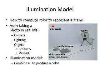
Ambient Lighting Background Light A surface that is not directly exposed to a light source may still be visible due to the reflected light from nearby objects. Ia: intensity parameter of ambient reflection Ambient reflection is: • independent of viewing direction and surface orientation • depends on the surface properties eye
RGB multiplies separately Material Color Light Color Ambient Lighting • Not created by any light source • A constant lighting from all directions • Contributed by scattered light in a surrounding
Diffuse Lighting Light is scattered with equal intensity in all directions, independent of the viewing direction. The surface appears equally bright from any viewing angle. Ex: rough or grainy surfaces
Diffuse Lighting • Assume light bounces in all directions Diffuse surface
Surface Normal n Surface Normal n Surface Normal n L Diffuse Lighting Full Reflection Partial None
Ambient + Diffuse Diffuse Diffuse Lighting Material Color Light Color Ambient + Diffuse
Diffuse Lighting Lambert’s cosine law: The amount of radiant energy coming from any surface area dA in a direction fN relative to the surface normal is proportional to cosfN. radiant energy per unit time intensity = ------------------------------------- projected area cosfN / (dA cosfN) = constant N (surface normal) fN fN Radiant energy direction dA
Diffuse Lighting Background lighting with ambient light Iambdiff = kdIa kd : Fraction of the incident light that is to be scattered as diffuse reflections (diffuse reflection coefficient)
Diffuse Lighting Il,incident = Il cosq Il,diff = kd . Il,incident = kd . Il cosq kd . Il (N.L) if N.L > 0 Il,diff = 0.0 if N.L ≤ 0 L = (Psource-Psurf) / |Psource-Psurf| Ambient and point-source: ka . Ia + kd . Il (N.L) if N.L>0 Idiff = ka . Ia if N.L≤0 N (surface normal) q q L (to incident light source) A cosq A (area) cosq = N.L
Specular Lighting The incident light is reflected in a concentrated region around specular reflection angle. Ex: a bright spot on shiny surfaces
Ambient + Diffuse + Specular Specular Specular Lighting • Create shining surface (surface perfectly reflects) • Viewpoint dependent Material Color Light Color
Specular Lighting N – surface normal L – to light source R – direction of ideal specular reflection V – to viewer f – viewer angle relative to specular reflection direction if f=0, ideal reflector (mirror) N R L q q f V
Specular Lighting Sets the intensity of specular reflection proportional to cosnsf. ns: specular reflection exponent 100 or more => shiny near 1 => dull infinite => perfect reflector
Specular Lighting • A larger ns shows more concentration of the reflection
Phong Model W(q): specular reflection coefficient of the surface Il,spec = W(q) Il cosnsf opaque surface: W(q)=constant=ks (0.0-1.0) transparent surface: reflection is appreciable if q approaches to 900. N R L q Shiny surface (large ns) N R L Dull surface (small ns)
Phong Model cosf = V . R Il,spec = W(q) Il cosnsf ksIl (V.R)ns if V.R>0 & N.L>0 Il,spec = 0.0 if V.R<0 & N.L≤0 R = (2N.L)N - L N R L q q f V
Phong Model H: halfway vector between V and L H=(L+V) / |L+V| Replace V.R (cosf) by N.H (cosa) ksIl (N.H)ns if V.R>0 & N.L>0 Il,spec = 0.0 if V.R<0 & N.L≤0 Requires less computation H N R L a q f V
Diffuse and Specular Lightings I = Idiff + Ispec = kaIa + kdIl (N.L) + ksIl (N.H)ns
Multiple Light Sources I = Iambdiff + ∑nl=1 (Il,diff + Il,spec ) = kaIa + ∑nl=1Il (kd(N.L) + ks(N.H)ns)
Surface Light Emission Ex: light bulb, etc. • Position a directional light source behind the surface • Simulate the emission with a set of point light sources distributed over the surface Radiocity model can be used to model realistic surface emission.
Ambient + Diffuse + Specular + Emissive Surface Light Emission • Color is emitted by the material only + Ambient + Diffuse + Specular Material Emissive Color
Surface Light Emission Extending the Light Model: I = Isurfemission + Iambdiff + ∑nl=1fl,radatten fl,angatten (Il,diff + Il,spec ) 1/ (a0+a1dl+a2dl2) local fl,radatten(dl)= 1.0 infinity 1.0 if light source is not spotlight fl,angatten = 0.0 if Vobj.Vlight=cos a < cos ql (Vobj . Vlight )al otherwise kd . Il (N.Ll) if N.L > 0 Il,diff = 0.0 if N.L ≤ 0 ksIl max{0.0, (N.Hl)ns } if V.R>0 & N.L>0 Il,spec = 0.0 if V.R<0 & N.L≤0
Surface Light Emission Intensity Overflow: • If any term exceeds the maximum intensity, set the intensity to maximum. • Divide the intensity if each term by the magnitude of the largest term to scale intensities between 0.0-1.0 • Set negative intensities to 0.0.
RGB Color Il = (IlR, IlG, IlB) ka = (kaR, kaG, kaB) Ex: for blue component IlB,diff = kdBIlB (N.Ll) Il,spec = ksBIlB max{0.0, (N.Hl)ns}
Luminance Lightness or darkness of a color (Brightness) luminance = ∫visible fr(f) I(f) df f: frequency I(f): intensity of light component with frequency f that is radiating in a particular direction r(f): experimentally determined proportionality function that varies with f and illumination level Green component contribute most to the luminance Blue component contribute least to the luminance luminance = 0.299 R + 0.587 G + 0.114 B or luminance = 0.2125 R + 0.7154 G + 0.0721 B
Transparency Transparent: objects behind are seen Opaque: objects behind cannot be seen Translucent: objects behind appear blurred Transparent surfaces produce reflected and transmitted light. Translucent surfaces have both diffuse and specular transmission. Ray tracing can be used.
air air glass Light Refraction Snell’s Law: sin qr = (hi/hr) sin qi qi: angel of incidence hi: index of refraction for the incident material hr: index of refraction for the refracting material Ex: air: 1.0 glass: 1.61 N L R qi qi reflection hi hr qr refraction T
Light Refraction T = [(hi/hr) cos qi - cos qr] N - (hi/hr)L Gives realistic effect but requires calculation • Ray tracing N L R qi qi reflection hi hr qr refraction T
Light Refraction Ignoring path shift due to refraction: I = (1-kt) Irefl + ktItrans Itrans: transmitted intensity Irefl: reflected intensity kt: transparency coefficient 1.0 – transparent 0.0 – opaque (1-kt): opacity factor N L R reflection qi qi hi hr qr T refraction
Light Refraction In Depth-Buffer Approach: • Process opaque surfaces first • Then, compare the depths of the transparent surfaces with the depth-buffer • If a transparent surface is visible, combine its intensity with the intensity that is previously stored in the frame buffer.
Atmospheric Effects fatmo(d) = e-rd or fatmo(d) = e-(rd)2 d: distance of the object to the viewing position r: to set a positive density value for the atmosphere Higher value means denser atmosphere, where colors are muted. Combining atmosphere color with the object’s color: I = fatmo(d) Iobj + (1- fatmo(d)) Iatmo
Shadows • Generated by a visible surface detection method • Surfaces that are visible from the view position are shaded according to the lighting model, which can be combined with texture patterns • Shadow areas are displayed with ambient light only or ambient light combined with textures
Polygon Rendering Constant-Intensity Surface Rendering Accurate in the following cases: • Polygon is not a section of a curved surface • All light sources are sufficiently far from the surface (N.L is constant) • Viewing position is sufficiently far from the surface (V.R is constant)
Polygon Rendering Gouraud Surface Rendering Linearly interpolates vertex intensities across the polygon faces. 1. Determine the average unit normal vector at each vertex of the polygon 2. Apply an illumination model at each polygon vertex to obtain the light intensity at that position 3. Linearly interpolate the vertex intensities over the projected area of the polygon