Download
1 / 26
260 likes | 395 Views
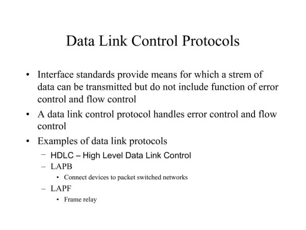
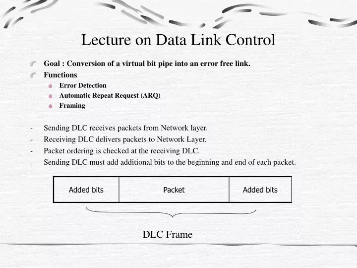
Lecture on Data Link Control. Goal : Conversion of a virtual bit pipe into an error free link. Functions Error Detection Automatic Repeat Request (ARQ) Framing Sending DLC receives packets from Network layer. Receiving DLC delivers packets to Network Layer.

E N D
Lecture on Data Link Control • Goal : Conversion of a virtual bit pipe into an error free link. • Functions • Error Detection • Automatic Repeat Request (ARQ) • Framing • Sending DLC receives packets from Network layer. • Receiving DLC delivers packets to Network Layer. • Packet ordering is checked at the receiving DLC. • Sending DLC must add additional bits to the beginning and end of each packet. DLC Frame
Error Detection • Virtual bit pipe is unreliable due to transmission errors. • Receiving DLC must detect errors. • If errors are detected, arrived packets are discarded and retransmission is requested. Note: Error correction is not usually done due to lack of knowledge on Physical Layer characteristics. Without specific knowledge on Physical Layer, error correction is not reliable.
Error Detection Method: Single Parity Check - Add one parity check bit to the packet to make the number of ones even (or odd). • Able to detect odd numbers of error. • Even numbered errors are not detectable. • Example : ASCII Code (7 bit data + 1 bit parity) 0 1 1 0 1 1 1 1 data bits parity bit
Error Detection Method: Horizontal and Vertical Parity Check Add one parity check for each row and one for each column. 1 0 1 1 1 1 1 0 1 1 0 0 0 1 1 1 0 1 0 0 1101x • x can be the parity check for the bottom row, the right most column, or the whole array of data including all previous parity bits. Order of transmission Original data
An odd number of errors in any row or column can be detected. • Four errors confined in two rows and two columns in the following manner cannot be detected 1 0 1 1 1 1 1* 0 1* 1 0 0 0 1 1 1 0* 1 0* 0 11011
Error detection method : Coding • Given the information bits S(0) S(1)…S(K-1), generate parity bits C(0) C(1)…C(L-1) with each C(i) depending on some information bits. • Transmit X(0) X(1)…X(K+L-1) where X(0)=C(0) X(1)=C(1) ………… X(L-1)=C(L-1) X(L)=S(0) X(L+1)=S(1) ……….. X(K+L-1)=S(K-1) Information bits Transmitted bits S(0) S(1)…S(K-1) | X(0) X(1)…X(K+L-1) 0 1 … 1 0 0 ... 1 …………… ……………. ………….. ……………. Each correctly generated X(0) X(1)…X(K+L-1) is called a codeword. There are 2K code words in the code book. However, there are 2K+L random bit patterns of length K+L that can potentially be received. 2K information patterns 2K code words
Automatic Repeat Request (ARQ) • After an error is detected, the receiving DLC requests the sending DLC to retransmit. • Assumptions • Framing is done properly • There exist a non zero probability that transmission is a success over the link. • FIFO on the communication link • All errors are properly detected.
Each packet below has the form above. Three popular methods of ARQ: • Stop and wait • Go back n • Selective repeat 1 2 3 4 5 Node A Time Space Node B
Stop and Wait ARQ Ensures correct transmission before next transmission. • Possible scenarios • Data may get lost : nothing happens at B • Data arrive at B with error : B sends Nak in Data+ • Data arrive at B without error : B sends Ack in Data+ • Ack received at A : A sends the next data • Nak received at A: A repeats the current data • A times out : A repeats the current data Data Sender A Data+ Receiver B Data+ is something that includes {Ack or Nak} and parity check.
Examples of Trouble Scenario timeout at A; repeat packet 0 0 0 Node A Ack Node B Packet 0 Packet 0 or 1? timeout at A; repeat packet 0 ack received for 0; But B thinks it’s for 1 0 0 1 2 Node A for 0 for 0 Packet 1 is lost Node B Packet 0
- Stop and Wait ARQ needs a certain ID system for data, ack, and nak. - Add SN and RN to the header of packets • SN : sequence number for the packet being transmitted at the sender • RN : sequence number of the next packet expected at the receiver • Correctness of stop and wait ARQ 1. Safety : Does not do anything incorrect • Packets are accepted only if they are error free • Packets are accepted only if they are the next one expected • Then, Stop and wait ARQ is safe 2. Liveliness : Never stops working For stop and wait ARQ, it is known that for the probability of transmission being a success greater than zero, we can show that t(1) < t(2) < t(3) < • t(1) : time when a packet is sent for the first time • t(2) : time when RN is incremented • t(3) : time when SN is updated • Then, Stop and Wait ARQ is live.
Go Back n ARQ • Sender does not wait. It can send n packets before acknowledgement is received. • Receiver acknowledges the receipt of the next packet expected. • Sender SNmin : smallest index not acknowledged. SNmax : smallest index not sent. • Receiver RN : next packet expected
0 1 2 3 4 5 Time out for packet 2 Window [0, 3] [2, 5] [4, 7] [5, 8] 0 1 2 3 4 5 2 4 5 SN Node A n = 4 Node B RN 0’ 1’ 2’ 3’ 4’ 5’ 6’ (piggy backed)
Selective Repeat ARQ In go back n, a single error causes round trip delay worth of retransmitted packets. • Need to store round-trip worth of packets • Probability of error in a packet is small. • Go back n ARQ is inefficient. • Selective repeat ARQ can achieve • Sender : Sends SNmin to SNmin + n –1 • Receiver : Accepts any RN to RN + n –1
Framing • Decides where a frame begins and ends • Three popular methods • Character-based • Bit-oriented • Length count
Character Based Framing SYN SYN DLE STX HEADER Packet DLE ETX CRC SYN SYN SYN • DLE is needed for differentiating accidental appearances of STX, ETX, and DLE itself • DLE STX : Start • * STX: binary string that happens to be the same as STX • DLE DLE STX : binary string that happens to be DLE STX • DLE DLE * : binary string that happens to be DLE * filler start Pay load EDD check filler
Disadvantages of Character-based Framing • The length of a packet must be integer multiple of character • High overhead • Accidental appearance of DLE ETX causes a packet to be terminated prematurely • CRC does not check • Loss of packet • Probability of a random CRC being accepted correctly = 2-L (L:length of CRC)
Bit Oriented Framing • Eliminates the need of having integer multiple of characters. • Replace DLE ETX with a string called flag. e.g., 0160 (01111110) To prevent the accidental appearance of the flag, bit stuffing is needed. → Every 11111 becomes 111110. → 01j for j > 6 corresponds to an abnormal termination
Overhead in Bit Oriented Framing Assumptions • Number of bits to be stuffed is small • 0 or 1 happens with the equal probability • 01j0 is the flag bit1 bit j-1 bit k xxxxxxxxxxxxxxxxxxxxxxxxxxxxxxxxxxxxxx Probability (stuff after bit i) = Note: we ignore the probability of having 01n for
Overhead Calculation OV : Number of overhead bits It is possible to find minimum Ek(OV) by varying j. Optimal value of
Length Field Framing Sends k (the number of bits in the frame) as part of the header For a given kmax, needs bits for transmitting the length field.
Minimum Bits for Length Field Let pk be the probability of a frame being of length k. If pk is uniform, H=log2 kmax If pk is geometric, H=log2 E(k)+log2 e Example) Geometrically distributed k Represent Encode the length as 01i r where r is represented in a binary string of j bits. If k=7 and j=2, • i=1 and r=3, 0111 To implement this, you need bits for each k
Effect of Maximum Frame Size • M:The number of total bits in a message • V:The number of overhead bits per frame • :The number of bits in a full frame without overhead • Large Total bits Number of frames Processing overhead
Small kmax (assume j nodes j-1 links) Source Destination Packet transmission time Total packet Delay over both links Time
Half-packet transmission time - Reduces the transmission delay by pipelining T: total time C: bits/second capacity on each link Total delay for the two half packets over both links Time
Stream Type Traffic: Voice • Delay calculation between the arrival of a bit to the delivery of this bit. • Assume the bits arrive as a packet of length k at bit rate of R/second • This packet needs to traverse a series of links at Ci bits/second. waiting time before transmission • Small k reduces T for finite queue