Download
1 / 27
270 likes | 414 Views
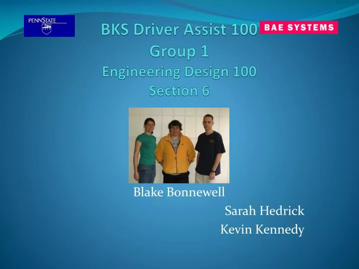
BKS Driver Assist 100 Group 1 Engineering Design 100 Section 6. Blake Bonnewell Sarah Hedrick Kevin Kennedy. Introduction.

E N D
BKS Driver Assist 100Group 1Engineering Design 100Section 6 Blake Bonnewell Sarah Hedrick Kevin Kennedy
Introduction Our team has been employed by BAE systems to follow a project scope to design a “Driver Assist” system consisting of different types of sensors( i.e., IR, LIDAR, Radar, etc.) that will be used by convoys in close vehicle spacing at high speeds on damaged or unimproved road surfaces. The system must detect and avoid obstacles while maintaining formation of three vehicles under blackout conditions.
Problem Statement There is no current system that convoy drivers can use in blackout conditions that gives information on presence of other vehicle’s range, velocity, and position, and detect obstacles in the road. Mission Statement By following specific design parameters develop an integrated system that detects vehicle range, velocity, and position in convoy operation at high speeds and close vehicle spacing during blackout conditions on unimproved road surfaces. All information must be displayed in a convenient way to inform the driver with warnings and suggested collision avoidance methods.
Customer Needs Assessment Hummers are fiber glass shells with no mirrors and no resistance from the elements. When it is raining outside it is raining inside. They travel at 60-65 mph with 150m between each vehicle. Drivers and TC have night vision with no depth perception. IR devices tend to shine against windows that create shadows. Vehicles only have small pin lights to keep detection low. 3 people 4 at most operate the vehicle. Space is extremely limited. Free space on ceiling, wheel wells, and corners. Detectors must be removable and reliable in all environmental elements. Compact Design to leave space for ammunition
Design Specifications The obstacle is a large crater 1 meter wide and deep, 2 meters in procession direction. Assume convoy velocity is 50 km/hr and 5 meters apart. There may be oncoming traffic that needs to be considered when creating a maneuver. Work in blackout conditions Work in all types of weather
Brainstorming Criteria • We wanted a 4-2 sensor system • It would be semi-automatic • Avoid sensors that wouldn’t work in the given conditions • Avoid video integration (depth perception, blackout, computing, algorithms, etc) • Explore a large range of possibilities
Brainstorming ideas 3 Sensor Setups 3 LIDAR 3 IR 2 LIDAR 1 IR 2 IR 1 LIDAR 3 RADAR RADAR IR LIDAR SONAR 2 RADAR GPS 2 LIDAR GPS 3 IR GPS RADAR LIDAR GPS RADAR IR 2 Sensor Setups 2 IR 2 LIDAR IR LIDAR RADAR LIDAR RADAR IR 2 RADAR 4 Sensor Setups • 4IR • 4LIDAR • 2IR 2 LIDAR • 4 Radar • 2Radar 2 IR • 2Radar 2 LIDAR • 1 GPS 1 RADAR 2 LIDAR • 1GPS 1 RADAR 2 IR • SONAR RADAR IR LIDAR • 2 RADAR 1 IR 1 LIDAR • 1 RADAR 2 IR 1 LIDAR • 1 Radar 2 LIDAR 1 IR • 1 GPS 1 RADAR 1 IR 1 LIDAR
Infrared Camera • Joystick Controlled Price: $8,900 • 11” W * 9” H * 9” D • Operating Temp: -40 C – 55 C • Depth of field: 450 Meters • Field of View 36 degrees • 360 continuous pan function • 16-40 degree tilt function • 45 second start up • Polarity- white = hot • 9V DC – 16V DC
LIDAR • 10” * 8” - < 29lbs Price: $20000-$50000 • Depth of field: 4-200m • Angle- 180-270, line and point • .05ms latency • 12V-16V at 4 Amps
RADAR • Back-Pack Size 70 lbs Price: $2500+ • Depth of Field: .2m-150m • 20 m -rain and heavy clutter • 30-50W power
Concept Generation Five Design concepts • 2 LIDAR 2 IR • 2 IR 2 RADAR 3. 2 IR 1 LIDAR 4. LIDAR RADAR 5. LIDAR IR RADAR
Best Design Selection 2 IR and 1 LIDAR • This system allows for us to accomplish the requirements of the project in the most efficient and effective manner • One of the Infra-Red sensors will be mounted on the front left corner of the vehicle. It serves to detect oncoming traffic, so that once the obstacle is detected the computer can make an informed choice as to recommend turning or stopping
Design cont. • The LIDAR sensor will be mounted front and center on the vehicle and will detect any changes in the road surface, i.e. a crater or IED • The other IR sensor will be rear mounted, and is to keep track of the rest of the convoy. • This system therefore accomplishes the tasks that are required of it • An extra battery, computer, and display will also be installed in the vehicle • System provides and audible and visual warning + information on how to best avoid obstacle
Cost Analysis • 2X 4000 Marine Pan-Tilt Thermal Imagers from SPI Corp. $8900 each • SICK LMS 211-30206 $26000 • Panasonic Toughbook 30 = 3,679.00 • Interstate Batteries 24V 18ah = 119.99 • Total = 47,598.99
Summary and Conclusion We concluded that our system array of 2 IR and 1 LIDAR was the best system as it allowed us to sense both oncoming, and rear oriented vehicles. While the LIDAR was capable of detecting obstacles in front of the Humvee all while exceeding our expectations. The driver should find the system more then adequate providing early notification giving the driver more then twice the normal needed reaction time to evade any oncoming obstacles.
Acknowledgments Xinli Wu was extremely helpful in facilitating information sessions having to do with sensors and customer needs. Our TA Matt Swingle was always available and willing to answer questions at anytime. Sgt. 1st Class Neumann provided us with information about current systems used on Humvees.
References • "Sensors." Tyco Electronics. 2008. 27 Apr. 2008 <http://www.macom.com/Markets/Automotive/sensors.asp>. • Spi Corp. 2002. 27 Apr. 2008 <http://www.nationalinfrared.com/4000_Marine.php>. • Mason, Richard, Jim Radford, Robert Walters, David Caldwell, Bill Caldwell, and DmitriyKogan, eds. Darpa Urban Challenge. 13 Apr. 2007. The Golem Group LLC. 27 Apr. 2008 <http://www.darpa.mil/GRANDCHALLENGE/TechPapers/The_Golem_Group.pdf>. • "High Definition LIDAR." Velodyne. 27 Apr. 2008 <http://www.velodyne.com/lidar/products/specifications.aspx>.


![[number 1-100]](https://cdn2.slideserve.com/4087213/number-1-100-dt.jpg)