Download
1 / 28
280 likes | 650 Views
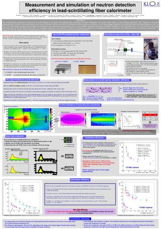
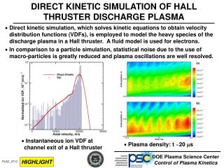
Study of the Plasma-Wall Interface – Measurement and Simulation of Sheath Potential Profiles. Samuel J. Langendorf, Mitchell L.R. Walker High-Power Electric Propulsion Laboratory, Georgia Institute of Technology, Atlanta, GA 30332 USA Laura P. Rose, Michael Keidar

E N D
Study of the Plasma-Wall Interface – Measurement and Simulation of Sheath Potential Profiles Samuel J. Langendorf, Mitchell L.R. Walker High-Power Electric Propulsion Laboratory, Georgia Institute of Technology, Atlanta, GA 30332 USA Laura P. Rose, Michael Keidar Micropropulsion and Nanotechnology Laboratory, George Washington University, Washington, D.C. 20052 USA Lubos Brieda Particle in Cell Consulting LLC, Falls Church, VA 22046 49th AIAA/ASME/SAE/ASEE Joint Propulsion Conference & Exhibit, 14 -17 July 2013, San Jose, California
Outline • Motivation • Background • Experimental Method • Simulation Method • Results & Discussion • Conclusions • Acknowledgements • Questions
Motivation • The interaction between the plasma and wall is critical in electric propulsion devices • Power Deposition Performance • Wall Erosion Lifetime
Background • Plasma-wall interaction: the plasma sheath Non-neutral region that forms near walls interacting with plasma to equalize fluxes of + and – charge. - Theory for floating wall, collisionless Argon plasma with cold ions
Background • Research objectives: • Experimentally characterize plasma-wall interactions • Develop predictive and efficient simulation capability • Validate theoretical models Enable designers to take advantage of plasma-wall interaction and not be hindered by it
Background • Where to start? • In HET’s, decreasing current utilization and electron temperature saturation with high SEE (BN) vs. low SEE (carbon velvet) discharge channel wall.1 1. Raitses, Y., et al. "Measurements of secondary electron emission effects in the Hall thruster discharge." Physics of Plasmas 13 (2006): 014502. Performance limitation due to wall interaction (SEE)
Experimental Method • To experiment with sheaths: Plasma cell • Multidipole-type plasma device selected • Proven2 • low ne, ni • Stability • In-vacuum Cusp shaped field Heated Filaments Aluminum Frame Permanent Magnets 2Lang, Alan, and Noah Hershkowitz. "Multidipole plasma density." Journal of Applied Physics 49.9 (1978): 4707-4710. Create thick-sheath plasma for interrogation
Experimental Method • Initial study: Measure sheath potential profile over wall material sample • Layout: Key: 3’ B W 2’ EP LP F M
Experimental Method • Plasma Cell, on
Simulation Method Simulate sheath and compare to experiment
Results & Discussion • Langmuir Probe
Results & Discussion • Emissive Probe Increasing Emission
Results & Discussion • Emissive Probe
Results & Discussion • Experimental Results, BN (HP) Filament Bias Voltage: -87 V
Results & Discussion Experimental Results, BN (HP) • Potential difference across the sheath is significantly larger than predicted using theory / measured Te • High-energy electron populations in multidipole plasma devices Electron kinetic effects are significant
Results & Discussion • Experiment vs. Simulation Filament Bias Voltage: -87 V
Results & Discussion • Simulated potential profiles agree with measurements within convolved experimental error when a potential drop is specified. Confirmed that electrostatics are driving the sheath structure in this case, not SEE or ion-neutral collisions.
Results & Discussion • Experimental Results, Al2O3 Neutral Pressure (Torr-Ar): 7.5 x 10⁻⁵ Filament Bias Below Ground
Results & Discussion • What causes the sheath disappearance? Filament bias voltage increased Primary electron energy increased Energy flux to Al2O3 surface increased Secondary electron emission increased Sheath potential drop decreased Sheath disappearance!
Results & Discussion • When does the sheath disappearance occur? • For Argon plasma, predicted to occur when wall SEE yield reaches 0.97. • Experimental electron temperatures are too low to elicit this yield, but high temperature electrons could. Electron kinetic effects are significant 3Viel-Inguimbert, V. "Secondary electron emission of ceramics used in the channel of SPT." IEPC-2003-258, Toulouse, France. 2003.
Results & Discussion • Experiment, BN vs. Al2O3
Conclusions • Observed sheaths in agreement with shape predicted by theory and simulation, but larger • Believed due to incomplete knowledge of EEDF • Experimentally verified that SEE can alter both size and shape of sheath potential profile and cause sheath disappearance • Mechanism for increased energy loss to the wall • Future Work • Improve Langmuir probe measurement to get EEDF • Incorporate measured EEDF into simulation • Measure SEE sheath with increased spatial resolution • Develop simulation of effects of SEE
Conclusions • Acknowledgements • This work is supported by the Air Force Office of Scientific Research through Grant FA9550-11-10160
Experimental Method Magnetic Field 200 180 160 140 120 100 80 60 40 20 Gaussmeter 1.6 1.4 1.2 1.0 0.8 0.6 0.4 0.2 0.0 Bulk plasma largely field-free Axial distance from magnet (in) (G) 0.0 0.2 0.4 0.6 0.8 1.0 1.2 Radial distance from magnet (in)
Background SEE Yield 3Viel-Inguimbert, V. "Secondary electron emission of ceramics used in the channel of SPT." IEPC-2003-258, Toulouse, France. 2003. Al2O3 = High SEE BN = Med SEE
Experimental Method • Plasma Cell