Download
1 / 30
320 likes | 514 Views
Multi-Pixel Optics Design for the Submillimeter Array(SMA). Yun- Chih Chou, Chao- Te Li, Ming-Tang Chen Institute of Astronomy and Astrophysics, Academia Sinica. Apr. 8, 2013 . Outline. SMA Introduction and Optics Multi-Pixel Upgrade Tryouts of Aperture Plane Array

E N D
Multi-Pixel Optics Design for the Submillimeter Array(SMA) Yun-Chih Chou, Chao-Te Li, Ming-Tang Chen Institute of Astronomy and Astrophysics, Academia Sinica
Apr. 8, 2013 Outline • SMA Introduction and Optics • Multi-Pixel Upgrade • Tryouts of Aperture Plane Array • Tryouts of Focal Plane Array • Conclusion The 24th International Symposium on Space Terahertz Technology, Netherlands
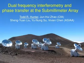
SMA Introduction • Full operation since 2005. • Antenna number: 8 • Antenna focal ratio (f/#): 14 (main dish diameter: 6m) • Current operation frequencies: 176-256GHz, 250-350GHz, 330-430GHz. • Dual polarization observation: 345GHz. • Field Of View: ~30” at 345GHz. Fig. SMA on Mauna Kea, Hawaii (elevation 4,045m)
Receiver Update • Receiver: Wide IF upgrade of 200GHz from 4-8 GHz to 4-12GHz. • All 8 antennas have wide IF 200GHz receivers now. • Wide IF upgrade of 300GHz from 4-8GHz to 4-12GHz followed up, and 3 receivers have been installed. Fig. Noise temperature (Trx) measurement of 300GHz SIS Junction tested in Dewar system.
SMA Optics • Design purpose: Simple frequency-independent optics. • Frequency-independent illumination on secondary reflector: All bands have common “virtual feed” behind receiver lens. • Design techniques: Fresnel imaging techniques, multi-mode Gaussian beam methods. Fig. SMA optics (top view).
SMA Optics - 2 • Relay optics: Two ellipsoidal mirrors. (beam waveguide M4 and M5) • Performance: Small coupling loss(M5 0.15% at 400GHz) and cross-polarization (-38dB at 3dB beam). • LO: Injection before feedhorn. • Receiver : Scalar horn and lens. • Feed Max gain: Max gain is reached when Bessel field of corrugated feedhorn is 10dB on aperture edge. Fig. Beam waveguide of SMA.
Multi-Pixel Upgrade • Advantage: Increase FOV and mapping speed. • Largest FOV w/o cryostat window limit: • Observation frequency: 345 GHz, key frequency.
Array Element • Array element: 7 (hexagonal). Design goal: • Feature frequency: 345 GHz • Least modification from current optics. • Aperture Plane Array or Focal Plane Array. • Requirement: High beam efficiency, small spillover etc.
SMA Optics Simulation • Simulation software: GRASP 10. • Simple optics of SMA 300 band receiver was established. • Simulation method: Gaussian beam propagation and Physical Optics (PO) calculation. • Reciprocity: Horn transmitter=receiver. Fig. SMA Optics simulated in GRASP.
GRASP Simulation Result • Beam efficiency: 84%, integrated to 12dB below peak. • Cross-polarization efficiency: 0.006%(-41dB) Fig. 2,3. Far-field grid of optics (Upper co-pol; right: Cx-pol.) Fig. 1. Far-field cut of SMA Optics.
Tryout 1 • Optics: RO unchanged. • Smaller lens due to aperture limit: Diameter reduced from 70mm to 25mm, so all beams are less truncated at cryostat window (diameter 76mm). • Lens radius 12.5mm corresponds to 0.9ω (Gaussian beam radius). • Feed spacing: 25mm. Fig. Tryout 1 optics with off-axis Gaussian beam passing through the cryostat window.
I – Simulation Result Fig. Tryout 1 far-field beam grid of 3dB and 6dB. Lens truncation reduced beam efficiency by 30%. Fig. Far-field cut of off-axis beam.
Tryout II • Goal: Make beams smaller to reduce lens truncation. • Feedhornand RO were changed to make beam radii smaller at lens and cryostat window positions. • Lens radius: 12.5mm, 1.25ω. Fig. Relay Optics of original SMA optics (left) and tryout#2 optics (right). M5 has new geometry and position in this solution.
II- Simulation Result • Beam efficiency of on-axis feed increased to over 70%, but off-axis fell dramatically due to spillover at subreflector. Fig. Off-axis feed 25mm away from propagation axis. Fig. Tryout 2 far-field beam grid of 3dB and 6dB.
Tryout III • RO: Removed. • Focusing element: The original insert lens to focus feedhorn signal. • Focus matching: Place beam waist of feed-lens set at the Cassegrain Focal point. • Min. feeds spacing: 2.44 * f/# * λ = 29.7 mm.
III - Feeds Spacing • Design feeds spacing: 45mm.
III – Largest FOV • Increase Pixel #: From 7 to 19. • FOV: From 5.5’ to 9.2’. • Beam efficiency of outermost pixel becomes 65.9% and 65.3% at 12dB.
Tryout IV • RO: Two big identical lenses. • F of RO lenses: 780.8mm. • Lens diameter: 250mm. • Optical path: Same as original, but replace ellipsoidal mirrors with flat mirrors. • f/# unchanged. • Feeds spacing: 45mm. Fig. Tryout 4 Optics.
IV: Simulation Result • On- and Off-axis efficiency: 70.6% and 67.1%.
Tryout V • RO: Two identical off-axis ellipsoidal mirrors • f 780.8mm, diameter 250mm. Incidence angle 14 deg. • f/# unchanged. • Cabin Restriction: Place two mirrors between M3 and M6. • Optical path: . Optical insert is removed to shorten optical path. • M6: Moved to right above receiver insert. Fig. Tryout 5 Optics.
Conclusion • 5 Tryouts of SMA 7-pixel upgrade were designed. • Possible solution is tryout 5. Distance from the second ellipsoidal mirror to insert lens is shortened. * Original optics simulated in GRASP has beam efficiency 84% at 12dB beam.
Future Task • Receiver design: Using current SMA 300GHz rx as a single-pixel prototype. Putting together rx components in 45mm spacing. • New mixer block design: Change to couple LO after feedhorn. • Realization in current Cabin: Spare space and cryostat window issue etc.
Please Comment. Thanks for your attention Yun-Chih Chou (Joy) 周允之 ycchou@asiaa.sinica.edu.tw