Download
1 / 55
550 likes | 566 Views
Learn about heat loss, energy use, and construction of UK walls for efficient energy conservation in low carbon buildings. Find out how U-values impact insulation choices for better energy management.

E N D
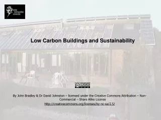
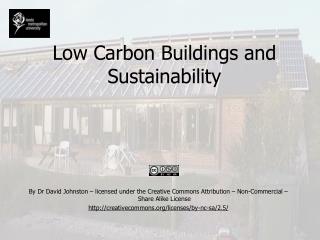
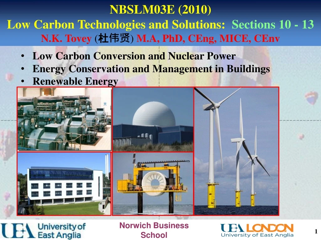
NBSLM03E (2010) Low Carbon Technologies and Solutions: Sections 10 - 13 N.K. Tovey (杜伟贤) M.A, PhD, CEng, MICE, CEnv • Low Carbon Conversion and Nuclear Power • Energy Conservation and Management in Buildings • Renewable Energy
NBSLM03E (2010) Low Carbon Technologies and Solutions N.K. Tovey (杜伟贤) M.A, PhD, CEng, MICE, CEnv • Energy Conservation in Buildings: The Basics • Heat Loss Calculations • Energy Management • Carbon Emission Factors Lecture 2 2 2
Intrinsic Energy Use provision of comfortable thermal environment Functional Energy Use energy use associated with specific activities in building at time. Intrinsic Energy Use(mostly associated with heating) will vary little with different uses (apart from specifics e.g. warehouses, sports complexes etc). Functional Energy Usewill vary depending on use – e.g. office (high computer use), laboratory (equipment), supermarket, hotel etc. In a poorly insulated building, functional energy use over life time will be low as a percentage In a well insulated building, functional energy can be the dominant use – representing over 50% in the ZICER Building at UEA. Energy Conservation in Buildings: The Basics 3
Heat Loss / Heat Gain Three forms of heat transfer Conduction Radiation Convection For buildings - conductive losses are main issue to address in heat loss/heat gain. Energy Conservation in Buildings: The Basics d Q T1 T2 Temperature Profile Heat Flow is proportional to temperature difference A T1 T2 4
Construction of Typical UK Walls: Solid Walls – most houses built pre-war. Energy Conservation in Buildings: The Basics plaster Brick In addition to resistance of brick and plaster there is: Internal surface resistance External surface resistance 5
Construction of Typical UK Walls: Solid Walls – most houses built pre-war. Energy Conservation in Buildings: The Basics 13 mm Brick 220 mm U-value is amount of heat transferred per sqm for a unit temperature difference between inside and out. It is the reciprocal of aggregate resistance. R = rbrick + rplaster + rint + rext But resistance = as A = 1.0 k for brick ~ 1.0 W m-1 oC-1 rbrick = 0.22 / 1.0 = 0.22 m2 oC W-1 For plaster k = 0.7 W m-1 oC-1 so rplaster = 0.013/0.7 = 0.02 m2oC W-1 Total resistance = 0.22 + 0.02 + 0.123 + 0.055 = 0.418 m2 oC W-1 So U- value = 1 / 0.418 = 2.39 W m-2 oC-1 6
Construction of Typical UK Walls: post war Energy Conservation in Buildings: The Basics cavity plaster Brick Brick Cavities provide an extra air-space and hence extra resistance to heat flow. 7
Construction of Typical UK Walls: post war Energy Conservation in Buildings: The Basics cavity plaster 110 mm Brick Brick • Components of resistance • Internal surface • Plaster • Brick • Cavity • Brick • External Surface • rinternal = 0.123 • rplaster = 0.013 / 0.7 = 0. 02 • rbrick = 0.11 / 1 = 0.11 • rcavity = 0. 18 • rbrick = 0.11 / 1 = 0.11 • rexternal = 0.055 Total resistance = 0.123 + +0.02 + 0.11 + 0.18 + 0.11 + 0.055 = 0.598 m2oC W-1 U – value = 1 / 0.598 = 1.67 W m-2 oC-1. Or 70% of solid wall. 8
Construction of Typical UK Walls: post ~ 1960 Energy Conservation in Buildings: The Basics cavity plaster 110 mm Block Brick • Components of resistance • Internal surface • Plaster • Block • Cavity • Brick • External Surface • rbrick = 0.11 / 1 = 0.11 • rblock = 0.11 / 0.14 = 0.76 • rplaster = 0.013 / 0.7 = 0. 02 • rexternal = 0.055 • rinternal = 0.123 • rcavity = 0. 18 Total resistance = 0.123 + +0.02 + 0.76 + 0.18 + 0.11 + 0.055 = 1.248 m2oC W-1 U – value = 1 / 1.248 = 0.8 W m-2 oC-1. Or 50% of brick / cavity / brick wall. 9
Construction of Typical UK Walls: post ~ 1960 Energy Conservation in Buildings: The Basics Cavity insulation plaster 110 mm Block 50 mm Brick • Components of resistance • Internal surface • Plaster • Block • Cavity insulation • Brick • External Surface • rbrick = 0.11 / 1 = 0.11 • rblock = 0.11 / 0.14 = 0.76 • rplaster = 0.013 / 0.7 = 0. 02 • rexternal = 0.055 • rinternal = 0.123 • rcavity insulation = 0.05/0.04 = 1.25 Total resistance = 0.123 + +0.02 + 0.76 + 1.25 + 0.11 + 0.055 = 2.318 m2oC W-1 U – value = 1 / 2.318 = 0.43 W m-2 oC-1. Or 50% of uninsulated brick / cavity / block wall. Brick / cavity / brick wall with insulation has U – Value = 0.59 W m-2oC-1 10
U – values for non-standard constructions can be estimated in a similar way U – values are tabulated for standard components U – value single glazing ~ 5.0 – 5.7 W m-2 oC-1 U – value double glazing ~ 2.5 – 2.86 W m-2 oC-1 Floors – typically 1.0 unless there is insulation. Roofs – depends on thickness of insulation Uninsulated post war ~ 2.0 W m-2 oC-1 25 mm - 0.89 W m-2 oC-1 50 mm - 0.57 W m-2 oC-1 100 mm - 0.34 W m-2 oC-1 150 mm - 0.25 W m-2 oC-1 200 mm - 0.18 W m-2 oC-1 250 mm - 0.15 W m-2 oC-1 Energy Conservation in Buildings: The Basics There are diminishing returns after first ~ 100mm and other conservation strategies become more sensible both economically and in carbon savings. 11
Ventilation in poorly insulated buildings may be only 25 – 30% of losses In well insulated buildings may be > 80% of total heat losses. >> ventilation heat recovery – e.g. ZICER. Ventilation occurs Through door/window opening Through crack around windows / doors / floors Through fabric itself Through vents, chimneys etc. Adequate ventilation is required for health Covered by specifying a particular number of air-changes per hour (ach) i.e. whole volume is changed in an hour. In a typical house 1 – 1.5 ach In a crowded lecture room may need 3 – 4 ach Energy Conservation in Buildings: The Basics 12
Ventilation: equivalent parameter to U-value i.e. Proportional to temperature difference Volume * ach * specific heat of air / 3600 W m-2 0C-1 Specific heat: quantity of energy required to raise temperature of unit mass (volume) of material by 1 degree. For air, specific heat ~ 1300 J m-3 Ventilation heat loss rate = volume * ach * 1300/3600 = 0.361 * ach * volume Energy Conservation in Buildings: The Basics 13
NBSLM03E (2010) Low Carbon Technologies and Solutions N.K. Tovey (杜伟贤) M.A, PhD, CEng, MICE, CEnv • Energy Conservation in Buildings: The Basics • Heat Loss Calculations • Energy Management • Carbon Emission Factors Lecture 2 14 14
Five components to heat loss / gain parameter Losses through Floor Roof Windows Walls Ventilation Heat Loss / Heat Gain Calculations Fabric Components: Area * U - value 20: Heat Loss / Heat Gain Calculations Ventilation: Volume * 0.361 * ach Total Heat Loss / Heat Gain Rate (H) H = ΣArea * U–value of fabric components + Volume * 0.361 * ach Heat lost from a building in a cool climate(or heat gained in warm climate) must be replaced (removed) by the heating(cooling) appliance – e..g boiler (air-conditioner) Heat to be replaced (removed) = H * temperature difference (inside – outside) 15
Design considerations: Heating/Cooling Capacity depends on internal and external temperatures. What should design temperature be? Internally – comfortable temperature – thermostat setting. Externally ? In internal temperature is set too high, sufficent heating will not be supplied in extreme conditions. But extra cost is often implied. Design External temperature in UK for heating –1oC In more extreme parts -30C is sometimes selected Heavy weight buildings do store heat to allow for some carry over to colder conditions. Heating appliances usually come in standard sizes – size to next size above requirement. Heat Loss / Heat Gain Calculations 16
Design considerations: Hot water heating is often provided by same source Provides an extra buffer for peak heating demand. Heating / Cooling must be designed to cope with peak design demand. Annual Energy Consumption Incidental gains arise from Body heat Lighting Hot water use Appliance use Solar gain Decrease / Increase overall annualheating (cooling) energy consumption – typically by several degrees. Heat Loss / Heat Gain Calculations 17
If incidental gains from all sources amount to 2250 watts, and the heat loss rate is 500 W C-1. Free temperature rise from incidental gains = 2250 / 500 = 4.5oC If thermostat is set at 20 oC, No heating is needed until internal temperature falls below 20 – 4.5 = 15.5 oC. 15.5oC is the neutral/base/or balance temperature. In UK and USA and used internationally the balance temperature for heating is on average 15.5oC (60oF). Each building is different and for accurate analysis, corrections must be applied. To allow rapid assessment of annual energy consumption Heating Degree Days (HDD)……Cooling Degree Days (CDD) There appears to be no standard for the base temperature for Cooling Degree Days but UKCIP02 uses 22oC Heat Loss / Heat Gain Calculations 18
Degree Days are an indirect measure of how cold or how warm a given period is. Used for estimating annual energy consumption. Heating Degree Days For every 1oC MEAN temperature on a particular day is below base temperature we add 1. For 10oC we add 15.5 -10 = 5.5 For -1oC we add 15.5 – (-1) = 16.5 For -10oC we add 15.5 – (-10) = 26.5 For days when MEAN temperatures above base temperature we do not add anything. Total Degree Days over a period is sum of all individual days Gives approximate estimate – see shaded box in hand out for more accurate method. Monthly Degree Days are published at www.vesma.com Heat Loss / Heat Gain Calculations 19
Annual Degree Days – East Anglia 20 year average 1959 – 1978 - 2430 20 year average 1979 – 1988 - 2351 20 year average 1988 - 2007 - 2182 Heat Loss / Heat Gain Calculations Example: 1 Heat Loss Rate (coefficient) is 450 WoC-1 What is estimated energy consumption for heating in January to March based on latest 20 year data = 450 * ( 337 + 303 + 272) * 86400 = 35.46 GJ Or 450 * (337 + 303 +272) * 24 / 1000 = 9850 kWh 86400 is seconds in a day 24 is hours in a day 20
Heat Loss / Heat Gain Calculations Boiler Output for a house during early January 1985. 10 9 8 7 6 5 4 3 2 1 0 20 15 10 5 0 -5 -10 Temperature oC Boiler Output (kW) 120 132 144 156 168 180 192 204 216 228 240 Hours 21
Heat Loss / Heat Gain Calculations If no heating is provided and mean external temperature is 20oC Internal temperature has a much lower amplitude and lags by several hours Can be used in effective management 22
Heat Loss / Heat Gain Calculations In morning period, boiler is full on during period, but throttles back during evening period 23
Heat Loss / Heat Gain Calculations With time switching – larger boiler is required to get temperature to acceptable levels 24
Large building in tropical country has 12000 sqm of single glazing Electricity consumption is as shown If Cooling Degree Days are 3000, and coefficient of performance of air-conditioner is 2.5, what is annual energy consumption? Heat Loss / Heat Gain Calculations Appliance / Base Load demand Cooling demand Gradient of cooling line is 75 kW /oC Annual consumption is 75 * 3000 * 24 = 5400 MWh If carbon factor is 800 kg /MWh Carbon emitted = 5400 * 800 / 1000 = 4320 tonnes 25
Gradient of line = 75 kWoC-1 actual heat gain rate = 75 *2.5 = 225 kW oC-1 must allow for COP of air-conditioner Installing double glazing reduces heat gain rate by: 12000 * ( 5 - 2.5) = 30 kW oC-1 U – values before and after double glazing Saving in electricity with be 30 /2.5 = 12 kWoC-1 Saving in electricity consumed = 12 *3000 * 24 = 864 MWh carbon saving = 864*800 / 1000 = 691.2 tonnes Heat Loss / Heat Gain Calculations 26
Annual electricity saved = 864 MWh - Annual carbon saved = 691.2 tonnes Marginal cost is 740 Paise/Unit - 9.328p per unit at Exchange Rate on 07April 2008 Total saving in monetary terms would be 864 * 1000 * 0.09328 = £80,594 per year With a life time of 30 years say, this represents a saving of £2.4 million A total of 25920 MWh saved and 20700 tonnes of carbon dioxide. If ‘K’ glass (low emissivity glass were installed) savings would be around 50% larger Heat Loss / Heat Gain Calculations Data for India 27
New house designed with heat loss rate of 0.2 kW oC-1 Two options Oil boiler - oil costs 45p/litre: calorific value 37 MJ/litre Heat Pump – electricity costs 4.5 per kWh Examine most cost effective option. Heat pump data as shown in graph. Heat Loss / Heat Gain Calculations Capital costs: Oil Boiler £2000, Heat Pump £4000 28
Heat Loss / Heat Gain Calculations Analysis is best done in tabular form Col (5) = 15.5 – col (2) Col (6) = 0.2 * col (5) * col (4) * 24 Col (7) = col (6) / col (3) Oil required 9456 kWh = 34042 MJ So 34042 / 37 = 920 litres are needed Cost of oil = 920 * 0.45 = £414 Cost of electricity for heat pump = 2658.5 * 0.045 = £119.64 and an annual saving of £294.36 Heat Loss Rate for house
Heat Loss / Heat Gain Calculations Annual saving in energy costs = £294.36 At 5% discount rate, cummulative discount factor over 10 years is 8.721735 So the discounted savings over life of project = 8.721735 * 294.36 = £2567.36 This is greater than the capital cost difference of £2000 (i.e (£4000 - £2000), there will be a net saving of £567.36 over the project life and the heat pump scheme is the more attractive financially.
NBSLM03E (2010) Low Carbon Technologies and Solutions N.K. Tovey (杜伟贤) M.A, PhD, CEng, MICE, CEnv • Energy Conservation in Buildings: The Basics • Heat Loss Calculations • Energy Management • Carbon Emission Factors Lecture 2 31 31
Energy Management: Electricity Consumption in a medium sized regional office of a large company Nearly double early 2005 level 33% higher than historic level Cost increase ~ £10000 - £12000 pa CO2 increase ~ 100 tonne per annum Appears to be associated with malfunction of air conditioner Electricity Consumption improves in late 2004 Implementation of conservation measures - Low Energy Lighting phased over autumn Sudden jump in consumption 32
Energy Management: Electricity Consumption of several offices of a large company 33
Energy Management: Electricity Consumption and Carbon Dioxide Emissions of several offices of a large company Annual Household consumption of Electricity in Norwich 3720 kWh 34
Basic analysis Aim: Assess overall energy performance of building Normalise to a standard time period Assess variation with external temperature Prediction Aim set targets for energy consumption following improvements Issues to address Convert all units to GJ or kWh for GJ multiply heat loss rate by Degree Days and number of seconds in a day (86400). for kWh multiply heat loss rate by Degree Days and number of hours in a day (24). Energy Management: Assessing Annual Consumption 35
Degree day method Quicker Oil & coal heating difficult – general estimates of consumption Mean temperature method More accurate Plot mean consumption against mean external temperature Energy Management: Assessing Annual Heating Requirements 36
Two component parts Temperature related Independent of temperature Hot water & cooking if by gas Total Energy = W + H*degree days*86400 W energy for hot water + cooking (gas) H is heat loss rate for the home Two unknowns W & H, Know degree days & energy consumption in two different periods of year Estimate heat loss & steady energy requirement Assessing Annual Heating Requirements: Degree Day Method 37
Energy consumption 2 successive quarters: 31.76 & 18.80 GJ Corresponding degree days: 1100 and 500 Total Energy consumed = W + H * degree days*86400 1100 * H * 86400 + W = 31.76 ………..(1) 500 * H * 86400 + W = 18.80 ………..(2) Simultaneous equations (subtract 2 from 1) H = (31.76 – 18.80) * 109 = 250 Watts (1100-500)*86400 Substitute for H in either equation to get W W = 31.76 * 109 - 1100 * 250 * 86400 = 8 * 109 = 8GJ Annual Heating Requirements: Degree Day Method - example H - heat loss W - hot water 38
Once H & W have been calculated Performance for subsequent quarters can be estimated If degree days for 3rd quarter = 400 Consumption predicted to be 400 * 250 * 86400 + 8 * 109 = 16.64 GJ H W If actual consumption is 17.5 GJ then energy has been wasted Annual Heating Requirements: Degree Day Method - example 39
Analysis of Energy Consumption Data in a Building – Degree Day Method There is a fair amount of scatter about trend line Lines drawn at 1.5 standard deviations above an below trend line Some consumption data points lie outside the band and should be classified as “Reporting Incidents” With time tighter deviation lines can be drawn 40
Electricity consumption varies during year. Base load for appliances and refrigeration Variable lighting Load depending on number of hours required for lighting Intercept is base load (A) Gradient is Lighting Load Parameter L Analysis of Lighting in a Building not heated by electricity Lighting Appliances and Refrigeration Installing Low Energy Lighting will decrease gradient by a factor 5 Installing more efficient appliances will reduce base load Installing both measures will reduce both L and A 41
Plot the mean consumption over a specific period against mean external temperature Generally more accurate than Monthly Degree Day Method as short term variations can be explored. With Daily readings, variations with day of week can be explored e.g. Weekend –shut down, do Mondays see extra consumption Analysis of Energy Consumption Data in a Building – Mean Temperature Method (not heated electrically) • Two parts to graph • Heating part represented by sloping line • Base load for cooking/hot water by horizontal line. • Do not merely do a regression line 42
Gradient of line is related to heat loss rate (coefficient) Adjust for boiler efficiency Multiply by to get heat loss rate (coefficient) – e.g. 70% for non condensing boiler, 90% for condensing boiler 300% for heat pump Efficiencies of all boilers are available on SEDBUK Database www.sedbuk.com/index.htm Analysis of Energy Consumption Data in a Building – Mean Temperature Method (not heated electrically) • Two parts to graph • Heating part represented by sloping line • Base load for cooking/hot water by horizontal line. 43
Analysis of Lighting in a Building not heated by electricity – An Example Data before conservation Intercept = appliance and refrigeration load (A). Gradient is Lighting load (L) Low energy lighting installed – should reduce L by 80% Actual data after installation Suggests that improvement of 80% is not achieved. If actual data are shown as blue line – improvements in energy management have taken place – or replacement of appliances with more energy efficient ones. 44
A – appliance Load W – water heating Load H – heat loss parameter L – lighting Load parameter More complex for analysis as both H & L are unknown Combine A & W to give overall appliance + hot water load (A*) E = (degree days * H + lighting hours * L) * 86400 + A* Where E = energy consumption 3 unknowns – H, L & A If we have data for 3 quarters Estimate values for H, L & A by solving 3 simultaneous equations If appliance load is known calculation is easier Actual analysis is beyond the scope of this scope, but the potential does exist. If more than three month data are available then opportunities for statistical analysis exist. Analysis of Heating and lighting in an electricilly heated Building – Method 1 45
Cumulative Deviation Method No energy conservation – horizontal line Winter following improved insulation Summer – no savings – heat conservation only Winter – parallel to 2 Summer - improved management of hot water Should be (4) + (5) but gradient is in fact less - energy conservation performance has got worse + Time + + + + + + + Cumulative Saving + + + + + + + + + + + + + + + + + + + + + + + + 4 6 3 2 1 5 Excess Saving Not as detailed as other methods, but good for displaying monetary savings in Lay Man’s terms 46
ANALYSIS OF BUILDING WITH HEATING AND COOLING Actual data from large residential building in Shanghai in 2006 Fudan University – Twin Tower All energy consumption is from electricity Gradients of lines 43.05 MWh per deg C per month heating 52.12 MWh per deg C per month cooling Assume 720 hours in a month 59.8 kWoC-1 heating and 72.4 kWoC-1 cooling =43.05/720 = 52.12/720 47
ANALYSIS OF BUILDING WITH HEATING AND COOLING Analysis of Energy Data - Fudan University – Twin Towers Neutral Temperature - 17.5oC Baseline consumption - 192.0 MWh/month Baselineconsumption Annual Heating Demand - 1675 MWh Annual Cooling Demand - 2515 MWh Annual Baseline (Functional) Demand - 2304 MWh Functional Energy Use is 35.5% of total energy use. 48
NBSLM03E (2010) Low Carbon Technologies and Solutions N.K. Tovey (杜伟贤) M.A, PhD, CEng, MICE, CEnv • Energy Conservation in Buildings: The Basics • Heat Loss Calculations • Energy Management • Carbon Emission Factors 49 49
Emission Factors for Fossil Fuels in UK Emission factors for Fossil fuels as used in the UK are available at: http://www.decc.gov.uk/en/content/cms/statistics/climate_change/gg_emissions/intro/intro.aspx. Single values if emission factors are quoted per unit volume or mass Two different values are quoted if specified in terms of energy content – e.g. GJ, kWh depending on whether Lower or Higher Calorific Value is used. Which calorific value should be used., If lower CV is used then emission factor is higher when specified in energy terms If higher CV is used the emission factor is lower when specified in energy terms Emission Factors 50