Download
1 / 41
410 likes | 563 Views
CS 152: Computer Architecture and Engineering Lecture 5 Hardware Description Languages, Multiple and Divide Randy H. Katz, Instructor Satrajit Chatterjee, Teaching Assistant George Porter, Teaching Assistant. Representation Languages. Hardware Representation Languages :

E N D
CS 152: Computer Architecture and EngineeringLecture 5Hardware Description Languages,Multiple and DivideRandy H. Katz, InstructorSatrajit Chatterjee, Teaching AssistantGeorge Porter, Teaching Assistant
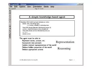
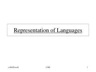
Representation Languages Hardware Representation Languages: Block Diagrams: FUs, Registers, & Dataflows Register Transfer Diagrams: Choice of busses to connect FUs, Regs Flowcharts State Diagrams Fifth Representation “Language”: Hardware Description Languages E.G., ISP' VHDL Verilog Descriptions in these languages can be used as input to simulation systems synthesis systems Two different ways to describe sequencing & microoperations hw modules described like programs with i/o ports, internal state, & parallel execution of assignment statements “software breadboard” generate hw from high level description "To Design is to Represent"
Simulation Before Construction • "Physical Breadboarding” • Discrete components/lower scale integration preceeds actual construction of prototype • Verify initial design concept • Simulation Before Construction • High level constructs implies faster to construct • Play "what if" more easily • Limited performance accuracy, however
Levels of Description Architectural Simulation Functional/Behavioral Register Transfer Logic Circuit Models programmer's view at a high level; written in your favorite programming language More detailed model, like the block diagram view Commitment to datapath FUs, registers, busses; register xfer operations are clock phase accurate Model is in terms of logic gates; higher level MSI functions described in terms of these Electrical behavior; accurate waveforms Less Abstract More Accurate Slower Simulation Schematic capture + logic simulation package Special languages + simulation systems for describing the inherent parallel activity in hardware
Verilog and VHDL(Hardware Description Languages) • Goals: • Support design, documentation, and simulation of hardware • Verilog is C like, VHDL is ADA/Pascal like • Digital system level to gate level • “Technology Insertion” • Concepts: • Verilog Module/VHDL Design Entity • Time-based execution model. Interface == External Characteristics Module/Design Entity == Logical entity implementedby a piece of hardware e.g., logic gate, 32-bit adder, memory subsystem Architecture (Body ) == Internal Behavior or Structure
Very Simple Verilog Model Example module add2bit (in1, in2, sum); input in1, in2; output[1:0] sum; wire in1, in2; reg[1:0] sum; always @(in1 or in2) begin sum = in1 + in2; $display (“The sum of %b and %b is %0d (time = %0d)”, in1, in2, sum, $time); end endmodule Interface: two inputs, one output • Continuous assignment, combinational logic, behavioral description • Variables can be of type reg, wire, integer, real, event, time Inputs are “wires”/interconnections, output is 2-bit “register”/mem elements Inputs are monitored, compute sum whenever they changeprint sum and simulation time
Structural Descriptions • Instances of “wired” lower level module within the current module … fulladd f1 (cin0, a0, b0, sum0, cout0) fulladd f2 (cout0, a1, b1, sum1, cout2) … b1 a1 b0 a0 f2 f1 cout2 cout0 cin0 sum1 sum0
Verilog Operators + - * / >= < <= ! && || == != ?: {} % === !== ~ & | << >> Arithmetic Relational Logical Logical equality Conditional Concatenate Modulus Case equality Bit-wise Shift • Operators borrowed from C programming language
Control Constructs IF-THEN-ELSE if (condition) block; else block; FOR for (i = 0; i < 4; i = i + 1) block; WHILE begin i = 0; while (i < 4) begin statement; statement; i = i + 1; end end CASE case (i) 0: statement; 1: statement; 2: statement; default: $stop; endcase Also casex, casez, repeat, forever
Clocking and Delays module repeat_loop (clock); input clock; initial begin repeat (5) @(posedge clock); $stop; end endmodule • Unlike conventional programs, not a serial model of execution • Global variable designates simulation time • Multiple events scheduled for execution at the same time • Execute all events for the current simulation time (in essentially a random order) before advancing to the next simulation time • New events generated as a by-product of execution and are added to the simulation pending queue Initial: execute at start of sim Wait for 5 positive clock edges Stop simulation
Clocking and Delays Synchronous: #expression – suspend execution for indicated time Asynchronous: @expression – suspend execution until event occurs Level: wait (expression) – suspend execution until expression true module time_control; reg[1:0] r; initial #70 $stop; initial begin : b1 //named block b1 #10 r = 1; //wait for 10 time units #20 r = 1; //wait for 20 time units #30 r = 1; //wait for 30 time units end initial begin : b2 //named block b2 #5 r = 2; //wait for 5 time units #20 r = 2; //wait for 20 time units #30 r = 2; //wait for 30 time units end always @r begin $display (“r= %0d at time %0d”, r, $time); end endmodule
Clocking and Delays Synchronous: #expression – suspend execution for indicated time Asynchronous: @expression – suspend execution until event occurs Level: wait (expression) – suspend execution until expression true module event_control; event e1, e2; initial @e1 begin $display (“I am in the middle.”); -> e2; end initial @e2 $display (“I am supposed to execute last.”); initial begin $display (“I am the first.”); -> e1; end endmodule
MIPS Arithmetic Instructions Instruction Example Meaning Comments add add $1,$2,$3 $1 = $2 + $3 3 operands; exception possible subtract sub $1,$2,$3 $1 = $2 – $3 3 operands; exception possible add immediate addi $1,$2,100 $1 = $2 + 100 + constant; exception possible add unsigned addu $1,$2,$3 $1 = $2 + $3 3 operands; no exceptions subtract unsigned subu $1,$2,$3 $1 = $2 – $3 3 operands; no exceptions add imm. unsign. addiu $1,$2,100 $1 = $2 + 100 + constant; no exceptions multiply mult $2,$3 Hi, Lo = $2 x $3 64-bit signed product multiply unsigned multu$2,$3 Hi, Lo = $2 x $3 64-bit unsigned product divide div $2,$3 Lo = $2 ÷ $3, Lo = quotient, Hi = remainder Hi = $2 mod $3 divide unsigned divu $2,$3 Lo = $2 ÷ $3, Unsigned quotient & remainder Hi = $2 mod $3 Move from Hi mfhi $1 $1 = Hi Used to get copy of Hi Move from Lo mflo $1 $1 = Lo Used to get copy of Lo
MULTIPLY (unsigned) • Paper and pencil example (unsigned): Multiplicand 1000Multiplier 1001 1000 0000 0000 1000 Product 01001000 • m bits x n bits = m+n bit product • Binary makes it easy: • 0 => place 0 ( 0 x multiplicand) • 1 => place a copy ( 1 x multiplicand) • Four versions of multiply hardware & algorithm: • Successive refinement
0 0 0 0 A3 A2 A1 A0 B0 A3 A2 A1 A0 B1 A3 A2 A1 A0 B2 A3 A2 A1 A0 B3 P7 P6 P5 P4 P3 P2 P1 P0 Unsigned Combinational Multiplier • Stage i accumulates A * 2 i if Bi == 1 • Q: How much hardware for 32 bit multiplier? Critical path?
Carry Save Addition of Four Integers • Add Columns first, then rows! • Can be used to reduce critical path of multiply • Example: 53 bit multiply (for floating point): • At least 53 levels with naïve technique • Only 9 with Carry save addition!
A3 A2 A1 A0 A3 A2 A1 A0 A3 A2 A1 A0 A3 A2 A1 A0 How Does It Work? 0 0 0 0 0 0 0 B0 • At each stage shift A left ( x 2) • Use next bit of B to determine whether to add in shifted multiplicand • Accumulate 2n bit partial product at each stage B1 B2 B3 P7 P6 P5 P4 P3 P2 P1 P0
Unsigned Shift-Add Multiplier (Version 1) • 64-bit Multiplicand reg, 64-bit ALU, 64-bit Product reg, 32-bit multiplier reg Shift Left Multiplicand 64 bits Shift Right Multiplier 64-bit ALU 32 bits Write Product Control 64 bits Multiplier = datapath + control
1. Test Multiplier0 Multiply Algorithm Version 1 Start Multiplier0 = 1 Multiplier0 = 0 • Product Multiplier Multiplicand 0000 0000 0011 0000 0010 • 0000 0010 0001 0000 0100 • 0000 0110 0000 0000 1000 • 0000 0110 1a. Add multiplicand to product & place the result in Product register 2. Shift the Multiplicand register left 1 bit. 3. Shift the Multiplier register right 1 bit. 32nd repetition? No: < 32 repetitions Yes: 32 repetitions Done
Observations on Multiply Version 1 • 1 clock per cycle => 100 clocks per multiply • Ratio of multiply to add 5:1 to 100:1 • 1/2 bits in multiplicand always 0=> 64-bit adder is wasted • 0’s inserted in left of multiplicand as shifted=> least significant bits of product never changed once formed • Instead of shifting multiplicand to left, shift product to right?
MULTIPLY HARDWARE Version 2 • 32-bit Multiplicand reg, 32 -bit ALU, 64-bit Product reg, 32-bit Multiplier reg Multiplicand 32 bits Shift Right Multiplier 32-bit ALU 32 bits Shift Right Product Control Write 64 bits
0 0 0 0 A3 A2 A1 A0 B0 A3 A2 A1 A0 B1 A3 A2 A1 A0 B2 A3 A2 A1 A0 B3 P7 P6 P5 P4 P3 P2 P1 P0 How to think of this? Remember original combinational multiplier:
A3 A2 A1 A0 A3 A2 A1 A0 A3 A2 A1 A0 A3 A2 A1 A0 Simply Warp to Let Product Move Right ... 0 0 0 0 • Multiplicand stay’s still and product moves right B0 B1 B2 B3 P7 P6 P5 P4 P3 P2 P1 P0
Start Multiplier0 = 1 Multiplier0 = 0 1. Test Multiplier0 1a. Add multiplicand to the left half ofproduct & place the result in the left half ofProduct register 2. Shift the Product register right 1 bit. 3. Shift the Multiplier register right 1 bit. 32nd repetition? No: < 32 repetitions Yes: 32 repetitions Done Multiply Algorithm Version 2 Product Multiplier Multiplicand 0000 0000 0011 0010 1: 0010 0000 0011 0010 2: 0001 0000 0011 0010 3: 0001 0000 0001 0010 1: 0011 0000 0001 0010 2: 0001 1000 0001 0010 3: 0001 1000 0000 0010 1: 0001 1000 0000 0010 2: 0000 1100 0000 0010 3: 0000 1100 0000 0010 1: 0000 1100 0000 0010 2: 0000 0110 0000 0010 3: 0000 0110 0000 0010 0000 0110 0000 0010
Start Multiplier0 = 1 Multiplier0 = 0 1. Test Multiplier0 1a. Add multiplicand to the left half ofproduct & place the result in the left half ofProduct register 2. Shift the Product register right 1 bit. 3. Shift the Multiplier register right 1 bit. 32nd repetition? No: < 32 repetitions Yes: 32 repetitions Done Still More Wasted Space! Product Multiplier Multiplicand 0000 0000 0011 0010 1: 0010 0000 0011 0010 2: 0001 0000 0011 0010 3: 0001 00000001 0010 1: 0011 00000001 0010 2: 0001 1000 0001 0010 3: 0001 10000000 0010 1: 0001 10000000 0010 2: 0000 11000000 0010 3: 0000 11000000 0010 1: 0000 11000000 0010 2: 0000 0110 0000 0010 3: 0000 0110 0000 0010 0000 0110 0000 0010
Observations on Multiply Version 2 • Product register wastes space that exactly matches size of multiplier=> combine Multiplier register and Product register
MULTIPLY HARDWARE Version 3 • 32-bit Multiplicand reg, 32 -bit ALU, 64-bit Product reg, (0-bit Multiplier reg) Multiplicand 32 bits 32-bit ALU Shift Right Product (Multiplier) Control Write 64 bits
1. Test Product0 1a. Add multiplicand to the left half of product & place the result in the left half of Product register Multiply Algorithm Version 3 Start Product0 = 1 Product0 = 0 Multiplicand Product0010 0000 0011 2. Shift the Product register right 1 bit. 32nd repetition? No: < 32 repetitions Yes: 32 repetitions Done
Observations on Multiply Version 3 • 2 steps per bit because Multiplier & Product combined • MIPS registers Hi/Lo are left/right half of Product • Gives us MIPS instruction MultU • How can you make it faster? • What about signed multiplication? • Easiest solution--make both positive & remember to comple-ment product if necessary when done (leave out the sign bit, run for 31 steps) • Apply definition of 2’s complement • Need to sign-extend partial products and subtract at the end • Booth’s Algorithm is elegant way to multiply signed numbers using same hardware as before and save cycles • Can handle multiple bits at a time
Motivation for Booth’s Algorithm • Example 2 x 6 = 0010 x 0110: 0010 x 0110 + 0000 shift (0 in multiplier) + 0010 add (1 in multiplier) + 0010 add (1 in multiplier) + 0000 shift (0 in multiplier) 00001100 • ALU with add or subtract gets same result in more than one way: 6 = – 2 + 8 0110 = – 00010 + 01000 = 11110 + 01000 • For example • 0010 x 0110 0000 shift (0 in multiplier) – 0010 sub(first 1 in multpl.) .0000 shift (mid string of 1s) . + 0010 add (prior step had last 1) 00001100
–1 + 10000 01111 Booth’s Algorithm middle of run end of run beginning of run 0 1 1 1 1 0 Current Bit Bit to the Right Explanation Example Op 1 0 Begins run of 1s 0001111000 sub 1 1 Middle of run of 1s 0001111000 none 0 1 End of run of 1s 0001111000 add 0 0 Middle of run of 0s 0001111000 none Originally for Speed (when shift was faster than add) • Replace a string of 1s in multiplier with an initial subtract when we first see a one and then later add for the bit after the last one
Booth’s Example (2 x 7) Operation Multiplicand Product next? 0. initial value 0010 0000 01110 10 -> sub 1a. P = P - m 1110 + 1110 1110 01110 shift P (sign ext) 1b. 0010 1111 00111 11 -> nop, shift 2. 0010 1111 10011 11 -> nop, shift 3. 0010 1111 11001 01 -> add 4a. 0010 + 0010 0001 11001 shift 4b. 0010 0000 1110 0 done
Booth’s Example (2 x -3) Operation Multiplicand Product next? 0. initial value 0010 0000 11010 10 -> sub 1a. P = P - m 1110 +1110 1110 11010 shift P (sign ext) 1b. 0010 1111 01101 01 -> add +0010 2a. 0001 01101 shift P 2b. 0010 0000 10110 10 -> sub +1110 3a. 0010 1110 10110 shift 3b. 0010 1111 0101 1 11 -> nop 4a 1111 0101 1 shift 4b. 0010 1111 10101 done
Current Bit to the Explanation Example RecodeBits Right 0 0 0 Middle of zeros 00 00 00 00 00 00 (0) 0 1 0 Single one 00 00 00 01 00 01 (1) 1 0 0 Begins run of 1s 00 01 11 10 00 10 (-2) 1 1 0 Begins run of 1s 00 01 11 11 00 01 (-1) 0 0 1 Ends run of 1s 00 00 11 11 00 01 (1) 0 1 1 Ends run of 1s 00 01 11 11 00 10 (2) 1 0 1 Isolated 0 00 11 10 11 00 01 (-1) 1 1 1 Middle of run 00 11 11 11 00 00 (0) Radix-4 Modified Booth’sMultiple Representations Once admit new symbols (i.e. 1), can have multiple representations of a number:
MIPS Logical Instructions Instruction Example Meaning Comment and and $1,$2,$3 $1 = $2 & $3 3 reg. operands; Logical AND or or $1,$2,$3 $1 = $2 | $3 3 reg. operands; Logical OR xor xor $1,$2,$3 $1 = $2 Å $3 3 reg. operands; Logical XOR nor nor $1,$2,$3 $1 = ~($2 | $3) 3 reg. operands; Logical NOR and immediate andi $1,$2,10 $1 = $2 & 10 Logical AND reg, constant or immediate ori $1,$2,10 $1 = $2 | 10 Logical OR reg, constant xor immediate xori $1, $2,10 $1 = ~$2 &~10 Logical XOR reg, constant shift left logical sll $1,$2,10 $1 = $2 << 10 Shift left by constant shift right logical srl $1,$2,10 $1 = $2 >> 10 Shift right by constant shift right arithm. sra $1,$2,10 $1 = $2 >> 10 Shift right (sign extend) shift left logical sllv $1,$2,$3 $1 = $2 << $3 Shift left by variable shift right logical srlv $1,$2, $3 $1 = $2 >> $3 Shift right by variable shift right arithm. srav $1,$2, $3 $1 = $2 >> $3 Shift right arith. by variable
Shifters Two kinds: logical-- value shifted in is always "0" arithmetic-- on right shifts, sign extend "0" msb lsb "0" msb lsb "0" Note: these are single bit shifts. A given instruction might request 0 to 32 bits to be shifted!
1 0 S2 S1 S0 A7 A6 A5 A4 A3 A2 A1 A0 1 1 1 1 1 1 1 1 0 0 0 0 0 0 0 0 1 1 1 1 1 1 1 1 0 0 0 0 0 0 0 0 1 1 1 1 1 1 1 1 0 0 0 0 0 0 0 0 R7 R6 R5 R4 R3 R2 R1 R0 Combinational Shifter from MUXes B A Basic Building Block sel • What comes in the MSBs? • How many levels for 32-bit shifter? • What if we use 4-1 Muxes ? D 8-bit right shifter
S 0 (0,1) S 1 (0, 2) S 2 (0, 4) S 3 (0, 8) General Shift Right Scheme Using 16 bit Example If added Right-to-left connections could support Rotate (not in MIPS but found in ISAs)
32 32 32 Funnel Shifter Instead Extract 32 bits of 64 • Shift A by i bits (sa= shift right amount) • Logical: Y = 0, X=A, sa=i • Arithmetic? Y = _, X=_, sa=_ • Rotate? Y = _, X=_, sa=_ • Left shifts? Y = _, X=_, sa=_ Y X Shift Right R Y X Shift Right R
SR3 SR2 SR1 SR0 D3 D2 A6 D1 A5 D0 A4 A3 A2 A1 A0 Barrel Shifter Technology-dependent solutions: transistor per switch
Summary • Introduction to Verilog (more in discussion sections!) • High level language to describe hardware • Module describes behavior or structure • Behavior can be higher level, e.g., x = boolean_expression(A,B,C,D); • Time units as an explicitly managed concept within description • Can activate modules when inputs change, not specifically invoked • Inherently parallel, need to understand implications of event scheduling • Multiply: successive refinement to see final design • 32-bit Adder, 64-bit shift register, 32-bit Multiplicand Register • Booth’s algorithm to handle signed multiplies • There are algorithms that calculate many bits of multiply per cycle (see exercises 4.36 to 4.39 in COD) • Shifter: successive refinement of 1/bit at a time shift register to barrel shifter