Download
1 / 12
120 likes | 134 Views
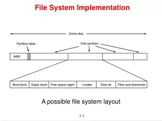
x ( t ). System Implementation. Identify the desire filter response (e.g. HP , LP , etc.) Determine the mathematical representation of the response H ( s ) Implement the filter circuit with RLC transistors and FETs. H ( s ). Circuit. y ( t ). Y ( s ) = X ( s ) H ( s )

E N D
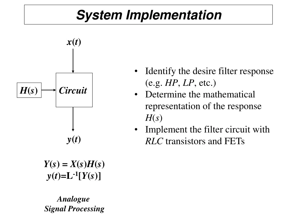
x(t) System Implementation • Identify the desire filter response (e.g. HP, LP, etc.) • Determine the mathematical representation of the response H(s) • Implement the filter circuit with RLC transistors and FETs H(s) Circuit y(t) Y(s) = X(s)H(s) y(t)=L-1[Y(s)] Analogue Signal Processing
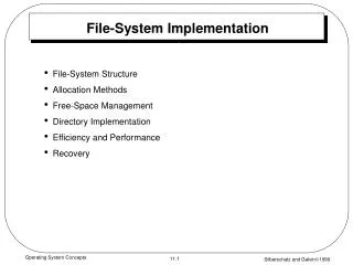
x(t) x(t) ADC System Implementation x(n) LTI Equation hFF(n)hFB(n) H(s) Circuit H(s) y(t) y(t) y(n) DAC y(n) = x(n)*hFF(n)+y(n)*hFB(n) Y(s) = X(s)H(s) y(t)=L-1[Y(s)] Analogue Signal Processing Digital Signal Processing
x(t) ADC System Implementation x(n) hFF(n)hFB(n) Impulse Response Time Response H(s) Transfer Function Frequency Response y(t) y(n) DAC y(n) = x(n)*hFF(n)+y(n)*hFB(n) H(s) ? Digital Signal Processing hFF(n) , hFB(n)
System Implementation • Two Problems: • How to find y(n)? • How to find H(z) from H(s)? x(t) ADC x(n) hFF(n)hFB(n) H(s) H(z) Z Transform y(t) y(n) DAC y(n) = x(n)*hFF(n)+y(n)*hFB(n) Solution to 1: A standardized equation for the class of linear time-invariant (LTI) systems.
System Implementation All LTI system have the following input/output relation Modifying parameters { M, NF, ak and bk} gives different responses (filtering functions).
System Implementation Remember an important property of z Transform
System Implementation Making use of the delay property, we have,
System Implementation b-NF z x(n) y(n) b0 + + z-1 z-1 a1 bNF z-1 aM
System Implementation z transform Note the similarity between the time and z domain
System Implementation Note the similarity between the time and z domain
NF M Sbk z-kX(z) Y(z) = Sak z-kY(z) + k= -NF k=1 System Implementation Specify filter characteristics (LP, HP, BP...) Determine transfer function H(z) Rarrange H(z) to the form
System Implementation How to determine H(z)? • Compute H(s) based on target frequency response. • Determine sampling frequency (period). • Convert H(s) to H(z). • Implement system based on the LTI structure.