Download
1 / 22
220 likes | 410 Views
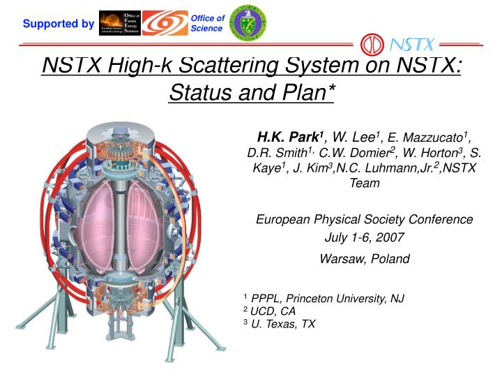
Office of Science. Supported by. NSTX High-k Scattering System on NSTX: Status and Plan*. H.K. Park 1 , W. Lee 1 , E. Mazzucato 1 , D.R. Smith 1, C.W. Domier 2 , W. Horton 3 , S. Kaye 1 , J. Kim 3 ,N.C. Luhmann,Jr. 2 ,NSTX Team European Physical Society Conference July 1-6, 2007

E N D
Office of Science Supported by NSTX High-k Scattering System on NSTX: Status and Plan* H.K. Park1, W. Lee1, E. Mazzucato1, D.R. Smith1, C.W. Domier2, W. Horton3, S. Kaye1, J. Kim3,N.C. Luhmann,Jr.2,NSTX Team European Physical Society Conference July 1-6, 2007 Warsaw, Poland 1PPPL, Princeton University, NJ 2 UCD, CA 3U. Texas, TX
NSTX plays a key role in extending fluctuation measurements beyond the present data base Scale length and Turbulence type • Full exploitation of turbulence based transport physics is the goal • Capability of investigating turbulence physics up to k┴ρe~0.7 • Multi-channel NSTX scattering system → k-space turbulence continuum through simultaneous measurement of five wavenumbers • Various operating regimes were studied – H/L modes, RS regime, High Te/Ti regime, confinement dependence on BT, Alfvén wave study → NSTX Hennequin et al. PPCF 46, 2004
Thomson CSF BWO Model CO 10-1 O-type backward wave oscillator (BWO) High power ~200 mW Frequency tunable 275-290 GHz ~15 MHz/V Lifetime: ~2000 hrs Siemel Power Supply High voltage: 12 kV Low ripple: < 15 mV Anode current controls BWO power output Cathode voltage controls BWO frequency Configured to lower BWO filament current between shots to conserve BWO lifetime BWO millimeter wave source and power supply Thomson CSF BWO High Voltage Lines Siemel Power Supply Cooling Lines F-band Waveguide Output
Probe beam launching hardware arrangement • Launcher system has three mirrors • Microwave power is piped through corrugated waveguide system Translation Across Entrance Window Motorized Linear Slide From Input Beam Splitter Spherical Focusing Mirror
Detection system hardware arrangement • Detection system is piped through corrugated waveguides • Detection array is located in the test cell base Windows for the Scattered signals Scattered signals From Input Beam Splitter To the wave-guide Array Spherical Focusing Mirror To detector array
Characteristics of the scattering system on NSTX • Tangential multi-channel (5) scattering system: • Po ~100 mW • lo ~1 mm (280 GHz) • System NF ~ 5000oK • System resolution • Dk= a/2 ~1.0 cm-1 Scattering length (Lv) Inboard ρ = 0.05 k┴ρe up to 0.7 Outboard ρ = 0.75 k┴ρe up to 0.4
Calibration of the System with A/O cell • Possible source of errors • Emissions from the plasma at the probe beam wavelength is negligible • Cross talk between channels is minimized by optical isolation • Calibration of the scattering system • Verification of the scattering length, relative efficiency curvature effect, magnetic shear effect and k-matching condition • Verification of the direction of waves
Verification of the propagation direction of the wave • Heterodyne detection system • Edge region – outward propagation direction is Positive frequency • Core region – outward propagation direction is Negative frequency outward Propagating wave Inward Propagating wave Frequency response from the probe beam at the edge region
Fluctuation of the Ohmic discharge (He) k┴ρe~0.1 • Monotonically decreasing power spectra as a function of wave-numbers in OH plasma • Plasma parameters • ne (0) ~ 2.5x1013cm-3 • Te (0) ~ 200eV • r/a ~0.85
Characteristics of H-mode edge plasma (pedestal) • Monotonically decreasing power spectra during L-mode phase • Non-monotonic power spectra during H-mode phase ETG?
Reduction of fluctuation is well correlated with improved confinement • Reduction of fluctuation at upper ITG/TEM and moderate changes at ETG during H-mode • Bursts of the scattered signal at the highest k is noted. • Ion transport is close to new classical in H-mode • Electron transport is reduced from L- to H-mode
Theoretical calculations Indicate ITG,TEM and ETG are possible candidates for electron transport • GS2 calculations indicatelower growth rate at lower k during H-mode phase and higher growth rates for all wavenumber during L-mode • Non-linear GTC results indicate ITG modes are stable during H-mode phase • ETG mode is unstablein L-mode and marginal in H-mode glin >> gExB during L-phase for all kqrs glin << gExB during H-phase for ITG/TEM glin ~ gExB during H-phase for ETG Experimental results are Consistent with the growth rate of ETG mode Other types of fluctuations???
Electron confinement dependence on BT • Confinement is improved at higher BT due to the improved electron transport at the edge region • The core electron thermal diffusivity increases at higher BT
Core experimental results Asymmetric spectral feature increases at higher field.
Edge experimental results Asymmetric spectral feature decreases at higher field.
Highly shifted frequency spectra (inside the pedestal of the H-mode) Highly shifted (inward propagating) turbulence spectra was observed during H-mode phase (inward propagating?) For the poloidal component: Negative frequency is electron diamagnetic direction r/a ~ 0.75 k┴ ~ 9.3 cm-1 k┴re ~ 0.22
L-mode discharge (high Te/Ti) by RF Frequency broadening during RF heating phase where Te is peaked at ~3 keV while Ti is at 1 keV
L-mode discharge (Te ~Ti) by RF+NBI Te is comparable to Ti and no spectral broadening during RF +NBI heating
Electrostatic component of the Alfvén wave Beta-induced Alfvén Acoustic Eigenmode (BAAE)
Summary • L-mode (k-4.3) and OH (k-3.7) plasmas - Monotonically decreasing fluctuation level extends the previous data base up to k┴ρe ~ 0.2 • H-mode plasmas • Reduction of fluctuations below k┴ρe << 0.1 (ITG/TEM) at the edge of the H-mode plasma is consistent with the improved confinement (k-3.4) • Enhanced fluctuations at higher k (above k┴ρe ~ 0.15) is observed in H-mode plasma (suppression of ETG in L-mode?) • Electron transport dependence on toroidal field strength • Enhanced fluctuation at the lower field at the edge and at the higher field at the core • Highly shifted frequency spectra inside the pedestal region but not in the core • Alfvén wave studies • BAAE mode was detected by scattering system • Highly broadened spectra at high Te/Ti ratio • Comparison study of discharges with RF alone and RF+NBI