Download
1 / 24
240 likes | 374 Views
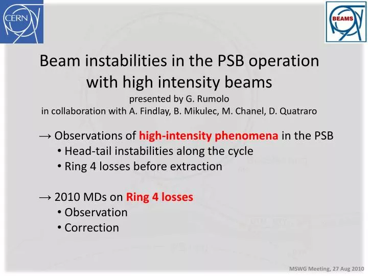
Beam instabilities in the PSB operation with high intensity beams presented by G. Rumolo in collaboration with A. Findlay, B. Mikulec , M. Chanel, D. Quatraro. Observations of high-intensity phenomena in the PSB Head-tail instabilities along the cycle Ring 4 losses before extraction

E N D
Beam instabilities in the PSB operation with high intensity beams presented by G. Rumolo in collaboration with A. Findlay, B. Mikulec, M. Chanel, D. Quatraro • Observations of high-intensity phenomena in the PSB • Head-tail instabilities along the cycle • Ring 4 losses before extraction • 2010 MDs on Ring 4 losses • Observation • Correction
The PSB instabilities…. • The beam is transversely stabilized in the PSB by a transverse feedback system • In particular, the feedback is necessary in the horizontal plane for high intensity beams (both h=1 and h=2) • In normal operation, the feedback is off in the vertical plane • What happens if the feedback system is switched off also in H? • Depending on the injected intensity, the beam can become unstable at different points along the cycle! N.B. Measurements were done on Ring 4, but actually these instabilities were seen to equally occur on all 4 rings From D. Quatraro’s talk in MSWG, 06/11/2009 Instability @ c=690ms Ithr ≈ 400 x 1010p (?) Instability @ c=378ms Ithr ≈ 300 x 1010p Instability @ c=478ms Ithr ≈ 500 x 1010p
Space charge • Measured tune spreads in the PSB • C=297ms is close after injection (50 MeV) • Other c-timings are @160MeV (lower tune spread due to energy, but shorter bunch) • C=656ms h=2 is on and bunch has been lengthened
Instability at c=370ms (I) Taking snapshots of the Dx,y signal along the bunch while the instability is developing, we can see 3 nodes
Instability at c=370ms (II) • In fact, the number of nodes has been found to depend on the beam intensity Lower intensity, 3 nodes Higher intensity, 2 nodes Decreasing trend of rise times with the bunch intensity
Instability at c=370ms (III) • Puzzling 2009 observations…. The bunch is ~600ns long at c=370ms Why do we see a D signal extending only over ~300ns? The signal comes from a wideband PU (the same used for the feedback) and goes through a BOSS unit
Instability at c=370ms (IV) • 2010 measurements (Aug 19th) show that, when we catch the instability at the very beginning of the evolution, we may indeed see only a part of the bunch • Later on, the signal gets saturated and its nodes usually become undistinguishable, but it clearly extends over the whole expected range of the bunch total length The D signal stretches over the bunch core at the beginning, then moves to the whole bunch
Instability at c=370ms (V) • What else did we learn from the 2010 MDs? • The radial position of the beam can influence this instability, as the beam tends to become more stable as we move it toward the inside of the machine • Both this instability and the one close to c=470ms exhibit no strong dependence on the bunch length and shape, and on the synchrotron tune. In fact, by turning on C04+C16 the two instabilities still appear at exactly the same points of the cycle. • A third instability at around c=407ms appears when we switch on C04+C16
Digression on the instability at c=407ms • We can clearly see the instability at c=407ms when we keep the horizontal damper on up until c=395ms (so that the beam can go through the first instability) • However, we quickly realized that this instability is strictly related to C16 • If C16 is on and with a voltage applied to the gap, we observe the instability • If C16 is on with 0 voltage, or it is disabled, or it is “disactuated”, the instability disappears (but we observe substantive beam induced voltage, up to 0.14 kV) • It is noted that the instability indeed occurs when there is a harmonic change in C16. Re-programming the C16 frequency function may eliminate the problem. Work ongoing (A. Findlay) –maybe this will also have an influence on the other instabilities??
Instability at c=370ms (theory & simulations) • According to Sacherer’s theory, with a chromatic shift of 5 MHz (xx ≈-1), the first unstable mode is n=6 and has a rise time of ~12ms for 500 x 1010p • This mode would appear due to resistive wall, as this is a low frequency impedance that is first sampled at a high value for bunch mode spectra moving to the negative frequencies. Sacherer’s theory 1st unstable mode Resistive wall impedance
Instability at c=370ms (theory & simulations) • Like theory, macroparticle simulations (not including space charge and using the total wake over several turns) would predict that, with a chromatic shift of 5 MHz (xx ≈-1), the first unstable mode is n=6 and has a rise time of ~10ms for 500 x 1010p • The simulation has considered classical resistive wall as source of excitation HEADTAIL simulations with multi-turn 6 nodes e-folding time ~10ms
Instability at c=370ms (theory & simulations) • Following Sacherer’s theory, a resonator impedance source would be expected to be able to excite only modes with n above 6 • However, HEADTAIL simulations reveal a more complex dynamics, with lower order head-tail modes that can be indeed excited by narrow-band resonators…. Strong instability followed by damping Resonator impedance 2-3 nodes The simulations assumed a resonator with parameters: Rt=2.5 MW/m, fr=1.6 MHz, Q=10 It is interesting to observe that the beam is stable for frequencies around 1.6 MHz (having scanned 1-2 MHz)
Instability at c=370ms (theory & simulations) • Why did we assume a narrow-band resonator at 1.6 MHz in our simulations? • A line at this frequency had been singled out on a spectrum analyzer during previous instability measurements at the PSB (M. Chanel, C. Carli) • This value is also likely to be associated to the lowest resonance due to the unmatched terminations on the PSB ejection kickers • We are currently trying to calculate the wake field of the kicker from CST-PS (C. Zannini) Measurements of the signal on the cables of the Ring 4 kicker (C. Carli, M. Chanel, et al, April 2010) Longitudinal Transverse Impedance of a C-magnet kicker with both cables on open circuits. Case of one module of the PSB ejection kicker (G. Nassibian, F. Sacherer, 1979). There is also a reference to this impedance as being responsible for horizontal instabilities in the PSB (H. Schönauer)
Instability at c=470ms • Also the second instability has the typical head-tail features • The number of nodes is higher (usually 4) and the rise time of this instability is typically longer than for the first one • In 2010 it was also observed like in 2009, and it showed little sensitivity to the mean radial position of the beam 4 nodes
Instability at c=690ms • Hard to recognize a specific head-tail mode from the D signal • The rise time of this instability is comparable to that of the first one
Instability at c=690ms • Losses at around the same time in the cycle were also observed in Ring 4 at the beginning of our MD on July 1st • They could be efficiently suppressed by reducing the gain of the phase loop between the cavities (non-ppm hardware change), and increasing the gain of the TFB. • No trace of this instability was observed in the MD of August 19th Attenuation reduced on the Ring 4 Once the problem of these losses was solved, the beam could be accelerated up until the last few ms. At this point our old friend, the loss during the last ms, re-appeared (From the PSB e-logbook July 1st Morning) See next slides….
Ring 4 losses before extraction • Even with the feedback system on, Ring 4 has suffered for years from an instability appearing right before extraction for intensities above 800 x 1010p • This instability would trigger the BLMs on the ejection line and stop the beam to ISOLDE Losses take place during the last 2 ms. They are associated to bunch shortening, but particles are also lost from the core
Ring 4 losses before extraction • The maximum intensity in Ring 4 was limited in operation to 800 x 1010p • C04 beam-loading, considered a potential responsible,was excluded during a dedicated MD last February, when C04 was short-circuited and the loss was not cured Almost half of the bunch is lost just before ejection
Ring 4 losses before extraction • The Wire Scanner measurements show some bizarre profiles during the instability in both transverse planes • The ‘second’ signal on the right side is measured shortly before extraction and could be a sign of instability or emittance blow up H profile V profile Extraction, the scan takes ~8ms to get to this point. The measurement of the ‘extra-beam’ starts ~2ms before.
Ring 4 losses before extraction • During the MD session on July 1st, after an adjustment of the beam radial position close to extraction (which removed a transient before the synchro), we attempted to change the working point at extraction in order to possibly cure the unstable motion that causes the beam loss • If the loss is caused by some resonance crossing enhanced by the space charge with high intensity, we can hope to move farther away from this resonance • If it is a coherent instability in the horizontal plane, we could suppress it by coupling more to the stable vertical plane (setting the tunes closer together) The GFA of the Ring 4 Q-strips (BR4.GSQCF) was extended and pulsed close to the end of the cycle. This had the effect of moving the tunes closer together
Ring 4 losses before extraction • Et voilà! • Finally we could accelerate up to almost 1000 x 1010p in Ring 4 without the BLMs being triggered
Ring 4 losses before extraction • We decided to adjust the working point at extraction in all 4 rings using the tune editor instead of the Q-strips • We basically programmed the H and V tunes to be equal at extraction (4.200) to enhance the coupling (they were before Qx=4.17 and Qy=4.23) • This could stabilize the beam in Ring 4 and allowed extraction of up to 1100 x 1010p!!! Programmed tunes Measured tunes
Ring 4 losses before extraction • M. Chanel went then back to the original working points at extraction and enhanced the coupling at extraction by using the skew quadrupole BR4.QSKH0 in Ring 4 • This setting proved to cure the losses at extraction, too. However, we are presently running with the modified working point at extraction and BR4.QSKH0 set to its original 0.78A • Consequently, we tend to believe that by bringing the tunes closer together we have actually stabilized the horizontal plane by coupling it to the stable vertical plane. 1.1 x 10¹³p accelerated and extracted with low losses in the ejection line
Summary & Conclusions • Severalcoherentinstabilitieshavebeenobservedthroughouttheyears in the PSB, usuallystartingfromthe horizontal plane • Up to thehighestintensitiesthatcanbeproduced in the4 Booster rings (i.e. 1000 x 1010 p/ring) thoselistedbelowcanbestabilizedusingtheTransverse Feedback System • An instability at aboutc=370ms shows a head-tailpatternwith 2-3 nodesand little (or no) dependence on thebunchshape and length. Seems to improvewhenthebeamisradiallymovedinwards. • An instability at aboutc=407ms iscorrelated to C16, and in particularwithitsharmonicchange. A newfrequencyprogramisunderstudy • An instability at aboutc=470ms exhibits a head-tailpatternwith 4 nodesand little (or no) dependence on thebunchshape and length, nor on the MRP • An instability at aboutc=690ms, with no distinctivepattern, which was stabilizedbyadjustingthegain of thephaseloopbetween C02 and C04. • Ifresistive wall was responsiblefortheseinstabilities, wewouldexpecthigher order modes to beexcited. Otherpotential impedancecandidates • Peakedimpedance at 1.6 MHz fromunmatchedterminations on theextractionkickercables • Cavities (C16 at somespecificfrequency?) • Wewouldlike to identify, and possiblyreduce, thesource of theseinstabilities to gainmorestabilitymarginwithrespect to thePSB intensityupgradewith Linac4! • TheRing4 instabilityshortlybeforeextraction, which has beenaffectingtheperformance of Ring 4 in the last years, was suppressedbychangingtheworking point at extraction and enhancingthecouplingbetweenthex and y planes.