Download

1 / 10
100 likes | 212 Views
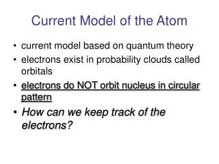
High Current Stabilization Circuit for Ultracold Atom Trap. Smita Speer, Howard University Mentor: Ryan Price, University of Maryland. Bose -Einstein Condensates in Lab. Rubidium atoms travel through Zeeman slower where atoms are slowed by the nearly resonant pump laser (780nm).

E N D
High Current Stabilization Circuit for Ultracold Atom Trap SmitaSpeer, Howard University Mentor: Ryan Price, University of Maryland
Bose-Einstein Condensates in Lab • Rubidium atoms travel through Zeeman slower where atoms are slowed by the nearly resonant pump laser (780nm). • Rb atoms enter the magneto- optical trap (MOT) where lasers in orthogonal direction are used to cool the atoms further and a magnetic field is applied as a restoring force to keep atoms in place. • Magnetic Trap is used to hold atoms while evaporative cooling reduces temperature of atoms to a few billionths of a degree above absolute zero [1,3]. Fig. 1. BCIT. 2003. BCIT MOT. [1] Cannon, Ben, Stone, Daniel, Price, Ryan. Light Analysis of Ultra-cold Magneto Optical Trap. [3] Steven Chu, The Manipulation of Neutral Particles. 1997. .
Effect on BECs • Fluctuations in the current result in changes in the magnetic fields used to hold ultracold atoms. • Magnetic traps are affected more noticeably by these fluctuations. • If the magnetic fields vary, the atoms can become too hot, scatter and ruin results [2]. [2] Lee, S. –K., Romalis, M. V., J. Appl. Phys. 103, 084904 (2008).
Current Fluctuation • The figure on the left is a breadboard in our lab used to measure how noisy our power source is and how it can be filtered by using bypass capacitors to stabilize voltage and power flow. • Storing energy • Blocking DC Fig. 2. Set up on breadboard in electronics lab Fig. 3. Electronics Bus. 2012. Bypass Capacitor Operation and Noise Ripple Characteristics
Operational Amplifier Configuration • We designed an op amp set up to provide more stable current used in our experiment. Liquid Cooling Plates Set Up within Mounting Rack PA05 HS18
Controlling Op Amp • To control the op amp, we designed a printed circuit board (pcb) to attach to the op amp’s pins. The pcb also offers us different ways to measure the current and compare with past methods for accuracy. • Components on the board further stabilize the current outputting from the op amp. • Resistors (current limit and compensation) • Capacitors (Bypass and compensation • Diodes and varistor (surge protection) Fig. 4. One of our resistors on a nickel
Set up within lab Current across op amp – current outputted Current outputted Op amp set up
Conclusions • Op amp design provides cleaner current. Can replace several supply coils in lab with external power source. • Future tests of system • Examine different methods of current measurement on pcb and on coils • Design separate box for increased precision of control of the current