Download
1 / 87
870 likes | 910 Views
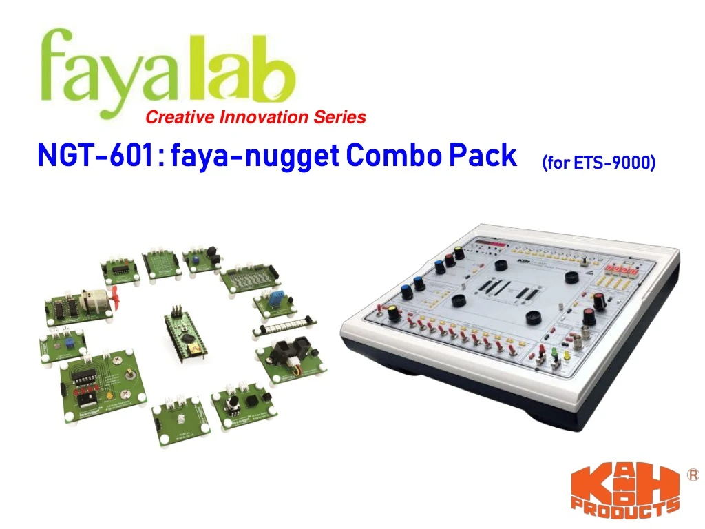
Explore a comprehensive faya-nugget Combo Pack designed for ETS-9000 experiments, covering topics like RGB LED, DC Motor, Basic Logic Gates, and more. Includes module lists, connections, code files, and exercise results.

E N D
Creative Innovation Series NGT-601 : faya-nugget Combo Pack (for ETS-9000)
Important Note! • For ALL experiments, please set the signal level switch to TTL position.
Suggest Learning Topic Order Appendix A Arduino Installation Basic RGB LED DC Motor Basic Logic Gates Appendix B faya Nano Overview IR Transmitter & Receiver Touch Slider Appendix C Nano Installation Step Motor Appendix D Brick Post Installation Light Sensor Appendix EBrick Cap Installation Humidity & Temperature Sensor Appendix FPower Wire Usage IR Distance Sensor Appendix GSignal Wires Usage Color Sticker IR Pulse Sensor Advanced Appendix HProject Setup
faya-nugget RGB LED DC Motor Touch Slider Basic Logic Gates Light Sensor IRTransmitter IRReceiver Step Motor Color Sticker Humidity and Temperature Sensor IR Distance Sensor IRPulse Sensor
RGB LED 1.7V ~ 5V 2.8V ~ 5V 2.8V ~ 5V Use R port to control intensity of Red LED Use G port to control intensity of Green LED Use B port to control intensity of Blue LED TopicSelect
Exercise RGB LED • Objective: • Using DataSwitches on ETS-9000 to control the status of RGB LED • Description: • SW7 turns ON Light up R • SW6 turns ON Light up G • SW5 turns ON Light up B • SW0 turns ON Light up R/G/B (Random) • Module List: • 1. fayaduino Nano x 1 • 2. RGB LED x 1 • 3.8 Bits Data Switches (ETS-9000) Check Result - click to play
Connection RGB LED
Source Code RGB LED File Name:rgb_led_1.ino L37~39 : (1) ransom(1,10) will return a random value between 1and 10. (2) The result of random(1,10)%2 will be either 1 or 0. (3) 1 = turn on LED ; 0 = turn off LED
Exercise Result RGB LED File Name:rgb_led_1.mov Click to play the movie
DC Motor • Input analog signal (DC voltage) at SIG port to control motor speed. • Input digital signal (HIGH/LOW) at DIR port to control motor direction. TopicSelect
Exercise DC Motor • Objective: • Using Pulse Switch and Data Switch to control the power and direction of the DC Motor • Description: • Pressing PA DC Motor turns ON • Releasing PA DC motor turns OFF • SW7 turns ON DC Motor run counter-clockwisely • SW7 turns OFF DC Motor run clockwisely • Module List: • 1. fayaduino Nano x 1 • 2. DC Motor x 1 • 3.8 Bits Data Switches (ETS-9000) • 4. Pulse Switch (ETS-9000) Check Result - click to play
Connection DCMotor
Source Code DCMotor File Name:dc_motor_1.ino L21 : analog value 900 = (900/1024) x 5 = 4.39V
Exercise Result DCMotor File Name:dc_motor_1.mov Click to play the movie
Basic Logic Gates HI/ LOW HI/ LOW …….. …….. HI/ LOW HI/ LOW This module provides a handy logic gates for the creation of combinational logic. TopicSelect
Exercise Basic Logic Gates • Objective: • Understand how to use Basic Logic Gates module • Description: • NOT Gate : Input = TTL Generator • Output = LED L0 • XOR Gate : Input = 2 Pulse Switch • Output = LED L3 • Module List: • 1. fayaduino Nano x 1 • 2. Basic Logic Gates x 1 • 3. Function Generator(ETS-9000) • 4. 8 Bits Data Switch (ETS-9000) Check Result - click to play
Connection Basic Logic Gates Important : You must connect Arduino GND to Function Generator GND to output signal.
Exercise Result Basic Logic Gates File Name:basic_logic_gates_1.mov Click to play the movie
Touch Slider Press Copper Pad HI Release Copper Pad LOW P7 P6 P5 P4 P3 P2 P1 P0 Red Blue Orange Green Red Blue Orange Green LOW LOW LOW LOW HI HI HI HI TopicSelect
Exercise Touch Slider • Objective: • Using fayaduino Nano and Touch Slider Module to create a tiny digital piano. • Description: • When touching one of the buttons on Touch Slider Module, the Arduino receive the signal and send corresponding frequency to the Speaker on ETS-9000 • Module List: • 1. fayaduino Nanox 1 • 2. Touch Slider x 1 • 3.Speaker (ETS-9000) Check Result - click to play
Connection Touch Slider
Source Code Touch Slider File Name:touch_slider_1.ino L18~L20: Create a note array storing the frequency of each notes. The value of the each not frequency is defined at pitches.h L32~L33: reading D5~D12 again and again L35: play corresponding note. For example, if D5 == HIGH P7 touched Play notes[0] = Note_C4 = DO if D8 == HIGH P4 touched Play notes[3] = Note_G4 = FA
Exercise Result Touch Slider File Name:touch_slider_1.mov Click to play the movie
IR Transmitter & Receiver start Transmitter Receiver After signal changes from HIGH to LOW, the module transmits serial signal from transmitter to receiver. TopicSelect
Exercise IR Transmitter& Receiver • Objective: • Using IR Transmitter and Receiver to transmit pulse data and show the result at 8 Bits LED Display on ETS-9000 • Description: • When pressing Pulse Switch PA, the LED lights upfrom 0 to 7 repeatedly • Module List: • 1. fayaduino Nano x 1 • 2. IR Transmitter x 1 • 3. IR Receiver x 1 • 4. Pulse Switch (ETS-9000) • 5. 8 BitsLEDDisplays (ETS-9000) Check Result - click to play
Connection IR Transmitter& Receiver
Source Code IR Transmitter& Receiver File Name:ir_transmitter_receiver_1.ino L33~43 : (1) interrupt service routine for interrupt pin D2 (2) counterFlag is same as digital pin connect to LED 0~7
Exercise Result IR Transmitter& Receiver File Name:ir_transmitter_receiver_1.mov Click to play the movie
Step Motor CCW CW Step : 1 2 3 4 A : 1 0 0 0 B : 0 1 0 0 A : 0 0 1 0 B : 0 0 0 1 Step Pulse • Input step pulse at four phase A, B, /A, /B to control the distance, speed, and direction of the Step Motor. • Rotor Step Angle (1-2Phase on) : 5.625° • Rotor Step Angle (1 Phase on ) : 11.25° • Gear Ratio : 64:1 • LED A, B, /A, /B represents the status of corresponding phase being driven. TopicSelect
Exercise Step Motor • Objective: • Using DataSwitches on ETS-9000 to control speed and direction of the Step Motor • Description: • SW0 turns ON/OFF rotate clockwisely / counter-clockwisely • SW1 turns ON speed + 100 • SW2 turns ON speed + 200 • SW3 turns ON speed + 300 • SW4 turns ON speed + 400 • Module List: • 1. fayaduino Nano x 1 • 2. Step Motor x 1 • 3.8 Bits Data Switches (ETS-9000) Check Result - click to play
Connection Step Motor
Source Code -1 Step Motor File Name:step_motor_1.ino L45~48 : Use SW0 to decide motor direction (HIGH = CW ; LOW = CCW) L50~54 : Use SW1~4 to decide motor speed SW1 speed +100 SW2 speed +200 SW3 speed +300 SW4 speed +400
Source Code -2 Step Motor File Name:step_motor_1.ino Use Arduino Stepper library [ #include<Stepper.h> ] to control step motor • motor.setSpeed(x) to set the motor speed • x is revolution per minute (RPM) for rotor. However, the gear ratio for this step motor is 1:64, as the result, the RPM for shaft is x/64. For example: • motor.setSpeed(768) = 768 ROM for rotor = 768/65 = 12 RPM for motor shaft = 60/12 = 5 sec per revolution • motor.step (y) to set motor moving steps • y is the number of steps. One revolution requires 2048 steps.
Exercise Result Step Motor File Name:step_motor_1.mov Click to play the movie
Light Sensor • Light Vout • Light Vout NC = No Connection • The value of output voltage Vout is proportional to the light intensity detected at light sensor. • Adjust the sensitivity of light sensor from resistor trimmer. TopicSelect
Exercise Light Sensor • Objective: • Using brickNano and Light sensor to measure light intensity. • Description: • The result of light intensity is measured and show at Digital Display from 00 to 99 on ETS-9000, the stronger the light intensity, the higher display value. • Module List: • 1. fayaduino Nano x 1 • 2 Light Sensor x 1 • 3. Digital Display (ETS-9000) Check Result - click to play
Connection Light Sensor
Source Code - 1 Light Sensor File Name:light_sensor_1.ino A B C D DEC L16~L25: Create a Table to store BCD information
Source Code - 2 Light Sensor 0~99 0~1023 L48: Scale the light intensity from (0~1023) to (0~99)
Source Code - 3 Light Sensor • L65~L66 : Calculate tens and units digit of displayNumber • For example, if number = 24 • tens = 124%100 / 10 = 24 / 10 = 2 • units = 124 % 100 % 10 = 24 % 10 = 4 • For example, if distance = 57 • tens = 57%100 / 10 = 57 / 10 = 5 • units = 57 % 100 % 10 = 57 % 10 = 7
Source Code - 4 Light Sensor units tens Display Value = 69 cm L67~L78: D1, D0 from Digital Display to represent tens, units digit of the light sensor value.
Source Code - 5 Light Sensor L86~L98 : Use bcdTable to decode the decimal number into binary number.
Exercise Result Light Sensor File Name:light_sensor_1.mov Click to play the movie
Humidity & Temperature Sensor #include<dht.h>; dht11.temperature to request temperature data dht11.humidit to request humidity data TopicSelect
Exercise Humidity & Temperature Sensor • Objective: • Show Temperature and Humidity at Digital Display on ETS-9000 • Description: • When Data Switch = LOW Show Temperature at Digital Display • When Data Switch = HIGH Show Humidity at Digital Display • Module List: • 1. fayaduino Nano x 1 • 2. Humidity and Temperature Sensor x 1 • 3. Data Switch (ETS-9000) • 4. Digital Displays Check Result - click to play
Connection Humidity & Temperature Sensor
Source Code Humidity & Temperature Sensor File Name:humidity_temperature_sensor_1.ino L19 : Please copy the library [DHTlib] in your DVD to Arduino Library L54: Use function .read(DataPin) to read both temperature and humidity data L55: Use .temperature to store the temperature just read L56: Use .humidity to store the humidity just read
Exercise Result Humidity & Temperature Sensor File Name:humidity_temperature_sensor_1.mov Click to play the movie
IR Distance Sensor Vout Light Emitter Light Receiver • This device outputs the voltage corresponding to the detection distance. • Distance measuring range : 20 to 150 cm TopicSelect
Exercise IR Distance Sensor • Objective: • Using Nano and IR Distance Sensor to measure object distance. • Description: • The IR Distance Sensor detectsobject distance and show the result at Digital Display on ETS-9000. • Module List: • 1. fayaduino Nano x 1 • 2. IR Distance Sensor x 1 • 3. Digital Display (ETS-9000) Check Result - click to play