Download
1 / 94
940 likes | 1.22k Views
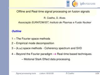
Digital Processing of Continous-Time Signals. Prepared by Dr M.Murugappan. Quote of the Day Optimist: "The glass is half full." Pessimist: "The glass is half empty." Engineer: "That glass is twice as large as it needs to be.". Topics Covered in this Chapter. Sampling of continuous signals

E N D
Digital Processing of Continous-Time Signals Prepared by Dr M.Murugappan Quote of the Day Optimist: "The glass is half full."Pessimist: "The glass is half empty."Engineer: "That glass is twice as large as it needs to be."
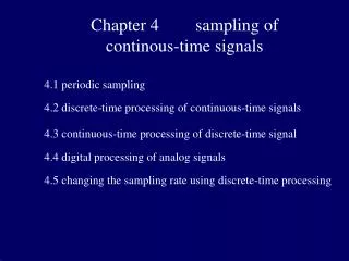
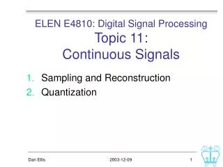
Topics Covered in this Chapter • Sampling of continuous signals • Sampling of Band pass signals • Analogue filter design • Anti-Aliasing filters • Analogue to Digital Convertors (ADC) • Digital to Analogue Convertors (DAC) Prerequisite: Basics of Signals and System, Fourier series, Signal processing operations, discrete and continuous time systems
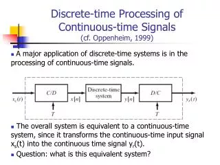
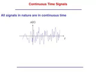
Overview • Most of the signals used in the real world are continuous in time (Ex: Speech, Music, Image) • Discrete time signal processing algorithms are used to implement in Discrete time analog or digital systems • Digital Systems: Discrete time signals are represented in binary form (0’s and 1’s) • Analog to Digital Convertors (ADC) and Digital to Analog Convertors (DAC) are used for converting continuous time analog signal into to discrete time digital and vice-versa. • Remarks: Hence, its necessary to develop the relations between the continuous-time signal and its discrete time equivalent in the time-domain and also in frequency domain.
Overview • Conversion of digital to analog or analog to digital signals are not only performed by ONLY using ADC and DAC. • It also need some additional circuits such as: • Anti-Aliasing Filter: • The bandwidth of continuous time signals are larger than the bandwidth of digital processors. • In order to avoid any aliasing (distortions), Anti-Aliasing filters are used before the Sample and Hold circuits. Anti-Aliasing Filter S/H Circuit ADC Digital Processor DAC Smoothing Filter Fig 1: Block diagram representation of the discrete time digital processing of a continuous –time signal
Overview • Sample and Hold Circuit (S/H): • It samples the input continuous-time signal at periodic intervals. • Holds the analog value constant at its output for sufficient time to ensure the accurate conversion by ADC. • used to maintain the ADC input as of constant magnitude until the conversion ends. • Analog to Digital Convertor (ADC): • Converts the input continuous-time signals to digital signals • Digital to Analog Convertor (DAC): • Converts the digital signal to continuous-time analog signal • Reconstruction (Smoothing) Filter: • Used to smooth out the DAC output
Overview • To recover the analog signal from sampled version, it should satisfy the Shannon’s sampling criteria. • If this criteria is not met out, an undesirable distortions affect the signal and it cannot be recovered back as original form. • Discrete time signals in many applications are generated by sampling continuous-time signals. Fig 2: A Simplified representation of Fig 1 Discrete time processor Ideal Interpolator Ideal Sampler
Periodic (Uniform) Sampling • Sampling is a continuous to discrete-time conversion • Most common sampling is periodic Ts is the sampling period in second fs = 1/Ts is the sampling frequency in Hz • Sampling frequency in radian-per-second s=2fs rad/sec • In general, the discrete signal is achieved by replacing the continuous variable “t” by “nTs”. • Use [.] for discrete-time and (.) for continuous time signals • This is the ideal case not the practical but close enough -3 -2 -1 0 1 2 3 4
Periodic Sampling • Consider the analog signal • The sampled signal is • The digital frequency = Analog frequency X sampling time • f = F.Ts • Sampling is, in general, not reversible • Fundamental issue in digital signal processing • If we loose information during sampling we cannot recover it • Under certain conditions an analog signal can be sampled without loss so that it can be reconstructed perfectly
Representation of Sampling • Mathematically convenient to represent in two stages • Multiplication of continuous time signal with periodic impulse train • Conversion of impulse train to a discrete time sequence p(t) Periodic impulse train Convert impulse train to discrete-time sequence ga(t) x g[n]=ga(nT), gp(T) Continuous Time signal ga(t) g[n] p(t) n t -3T -2T -T 0 T 2T 3T 4T -3 -2 -1 0 1 2 3 4
Effect of Sampling in Frequency Domain • Frequency domain representation of ga(t) is given by its Continuous-Time Fourier transform pair as: • The frequency domain representation of g[n] is given by discrete time FT: • To establish the relation between these two different types of Fourier Spectra, we treat the sampling operation mathematically as a multiplication of the continuous time signal ga(t) by a periodic impulse function p(t): • Note that multiplication in time is convolution in frequency
Effect of Sampling in Frequency Domain • Here, p(t) is the periodic impulse train and it can be represented in Fourier series as: Where ΩT = 2π/T = Angular sampling frequency • Therefore, = . • From the frequency shifting property of the CTFT, the CTFT of is given by .
Effect of Sampling in Frequency Domain • Therefore, CTFT of is given as: • Remarks: is a periodic function of frequency consisting of a sum of shifted and scaled replicas of , shifted by integer multiples of and scaled by 1/T. • When k=0, then we will obtain the baseband portion of and each remaining terms are the frequency translated portions of .
N -N s>2N 3s -2s s -N N s 2s 3s s<2N 3s -2s s -N N s 2s 3s Effect of Sampling in Frequency Domain • This tells us that the impulse train modulator • Creates images of the Fourier transform of the input signal • Images are periodic with sampling frequency • If T< 2Nsampling is irreversible due to aliasing of images
Low pass filter s>2N 3s -2s s -N N s 2s 3s s<2N 3s -2s s -N N s 2s 3s Effect of Sampling in Frequency Domain Periodic impulse train g[n]=ga(nT), p(t) Continuous Time signal Convert impulse train to discrete-time sequence Low Pass Filter (Hr(jΩ) ga(t) x ga(T)
Nyquist Sampling Theorem • Let ga(t) be a bandlimited signal with • Then gp(t) is uniquely determined by its samples g[n]= ga(nT), if • T is generally known as the Angular Sampling Frequency • mis highest frequency of ga(t) • The frequency 2m is called Nyquist rate Nyquist Sampling Condition
Nyquist Sampling Theorem • If the sampling frequency is higher than the Nyquist rate means, the sampling operation is referred as Over sampling. • If the sampling frequency is lesser than the Nyquist rate means, the sampling operation is referred as Under sampling. • If the sampling frequency is equal to the Nyquist rate means, the sampling operation is referred as Critical sampling. • Sampling Frequency in Real World Applications: • Digital telephone: 8 kHz (Conversation frequency is 3.4 kHz) • Compact Disc in Music systems: 44.1 kHz (for good fidelity systems require the bandwidth of 20 kHz)
Sampling of Bandpass Signal • Continuous time signal is obtained from the discrete time signal by uniform sampling • Assume that the spectrum of continuous time signal is bandlimited in the frequency range from DC to some frequency m . • This kind of continuous time signal are commonly referred to as low pass signals. • In some cases, the signal is bandlimited to a higher range where L >0. Band pass signal (its also obtained by modulating a low pass signal). • According to sampling criteria is to be achieved to prevent aliasing. • Limitations: (i) spectral gaps (ii) is very high – which is not practical.
Sampling of Bandpass Signal • Let define the bandwidth of the bandpass signal. • Assume that, the highest frequency contained in the signal is an integer multiple of the bandwidth, i.e • Now the sampling frequency to satisfy the Nyquist condition • Which is smaller than , the Nyquist sampling rate. • We know that, CTFT of gp(t) is • Substitute the value of in T
Sampling of Bandpass Signal • consists of sum of the original FT of and replicas of shifted by integer multiples of twice the bandwidth and then scaled by 1/T. • The amount of shift for each value of “k” ensure that there will be no overlap between all shifted replicas and hence no aliasing. • Integer value of M = No aliasing ; else aliasing • Therefore, ga(t) can be recovered from gp(t) by passing through an ideal bandpass filter with a passband given by and a gain of T.
Filter All real-world signals are sums of sinusoidal components having various frequencies, amplitudes, and phases. Filters process the sinusoid components of an input signal differently depending of the frequency of each component. Often, the goal of the filter is to retain the components in certain frequency ranges and to reject components in other ranges.
Applications of Filtering: • Noise suppression • Enhancement of selected frequency range • Bandwidth limiting • Removal or attenuation of specific frequencies
What is a filter? Simply put, it retains history of the input signal. Take this simple lowpass filter for an example. Vout Vin This simple filter is a kind of integrator, in which the capacitor integrates the charge provided through the resistor. As the rate of change of Vout depends on the current through the resistor, low frequencies will be filtered less than high frequencies.
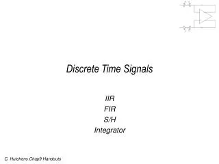
Analog Filter Filter FIR Filter Digital Filter IIR Filter Types of Filter • Basic filter classification • We put emphasis on the digital filter now, and will introduce to the design method of the FIR filter and IIR filter respectively.
Ideal magnitude frequency response Filter Specifications Ideal Filters Low-Pass Filters:Low-pass filters are designed to pass low frequencies, from zero to a certain cut off frequency and to block high frequencies.
Ideal magnitude frequency response Filter Specifications Ideal Filters Low-Pass Filters:
Ideal magnitude frequency response High-Pass Filters:High-pass filters are designed to pass high frequencies, from a certain cut off frequency to , and to block low frequencies.
Ideal magnitude frequency response High-Pass Filters:
Ideal magnitude frequency response Band-Pass Filters:Band-pass filters are designed to pass a certain frequency range, which does not include zero, and to block other frequencies.
Ideal magnitude frequency response Band-Pass Filters:
Ideal magnitude frequency response Band-Stop Filters:Band-stop filters are designed to block a certain frequency range, which does not include zero, and to pass other frequencies.
Ideal magnitude frequency response Band-Stop Filters:
Getting back to the analog filter: • The analog filter’s output can not change instantly as that would require infinite current in the resistor, that means that the output depends on the HISTORY of the signal. • How does the analog filter exhibit the memory? • In the case shown, the capacitor is the memory element. • It retains previous history. • It does so by summing the history into one value, the voltage across the capacitor. • In such a way, a single component can have a long memory.
Analog Filter to Digital Filter Analog filter : Infinitely long impulse response S – Z (complex-valued mapping) Digital IIR filter : Infinitely long impulse response
Analog Filter to Digital Filter • Other Design Approaches • Simultaneously approximate both the magnitude and the phase response • Require advanced optimization tools
Preliminaries On Analog Filters In some IIR filter design 1 2 3 1 2 3
Preliminaries On Analog Filters 0 0 Rp Magnitude (dB) Rs Transition band Passband Stopband 0 Wp Ws 1 Normalized frequency
Preliminaries On Analog Filters Analog lowpass filter specifications : passband ripple in dB : stopband attenuation in dB
Preliminaries On Analog Filters Lowpass filter Highpass filter Bandpass filter Bandstop filter Normalization convention:0 ≤ f ≤ 1 = Nyquist frequency
Preliminaries On Analog Filters Analog lowpass filter system function • Poles and zeros of magnitude-squared function are distributed in a mirror-image symmetry with respect to the imaginary axis • For real filters, poles and zeros occur in complex conjugate pairs ( mirror symmetry with respect to real axis)
Preliminaries On Analog Filters Analog lowpass filter system function • Pick up poles On LHP • Pick up zeros on LHP or • Imaginary axis Causal Stable
Analog Filter to Digital Filter • Advantages • Analog filter design tables available • Filter transformation (s – z) tables available • Frequency band transformation (s – s / z – z) available • Disadvantages • No control over the phase characteristics of the IIR filter • Magnitude – only design
Filter Design • IIR design methods • Butterworth filter • Butterworth, Chebyshev • Types I and II, elliptic filters • Order selection functions • Direct IIR methods Design specifications • Remove noise above • a cutoff frequency • Set passband ripple, • stopband attenuation, • or transition width • Minimize filter order • Arbitrary response Less specific More specific
IIR Filters Advantage: lower order than FIR designs Disdvantage: nonlinear phase …but see filtfilt • Classic IIR filters types • Butterworth • Chebyshev Types I and II • Elliptic • Bessel Supported in both the analog and digital domains (except Bessel – analog only), and in lowpass, highpass, bandpass, and bandstop configurations.