Download
1 / 66
670 likes | 1k Views
Biomedical Instrumentation II. Dr. Hugh Blanton ENTC 4370. ULTRASONOGRAPHY. Basic Principles of Ultrasound. Ultrasonic waves in the frequency range of 1 million to 10 million Hz are used in diagnostic ultrasonography.

E N D
Biomedical Instrumentation II Dr. Hugh Blanton ENTC 4370
ULTRASONOGRAPHY Dr. Blanton - ENTC 4370 - ULTRASONICS 2
Basic Principles of Ultrasound • Ultrasonic waves in the frequency range of 1 million to 10 million Hz are used in diagnostic ultrasonography. • The lower the frequency, the deeper the penetration and the higher the frequency, the more superficial the penetration. Dr. Blanton - ENTC 4370 - ULTRASONICS 3
The ultrasonic waves are transmitted into a medium in the form of a narrow beam. • Depending on the density of the medium, the sound waves are either • refracted, • absorbed or • reflected, Dr. Blanton - ENTC 4370 - ULTRASONICS 4
Basic Instrumentation • The sound waves are produced by electrically-stimulating crystals which are arranged within an instrument called a transducer. • There are various types of transducers in which the crystals are arranged differently so that when the crystals are stimulated they are “fired” at different frequencies for optimum penetration. Dr. Blanton - ENTC 4370 - ULTRASONICS 5
When the crystals are “fired”, a signal is sent out which strikes the tissues in the body. • Some of the waves are absorbed into the tissue, • some are bent or refracted and become scatter, and • some are reflected. • The reflected waves are sent back to the transducer as echoes. • The echoes are converted into electrical impulses and displayed on a computerized screen. • This becomes an image of the specific body area. Dr. Blanton - ENTC 4370 - ULTRASONICS 6
The sound waves can not travel into the body without a waterbased medium. • Ultrasound will not produce an image when traveling through air. • For this reason, a substance called acoustic coupling gel must be placed on the skin over the area to be imaged. • The gel blocks out air so the sound beam can penetrate the body. • The transducer is placed directly into the gel. Dr. Blanton - ENTC 4370 - ULTRASONICS 7
Usefulness of Ultrasound • In clinical practice today, ultrasonography may be divided into separate subgroups. • Each group consists of a special area of ultrasound. • These groups may be • general ultrasonography, • echocardiography and • vascular technology. Dr. Blanton - ENTC 4370 - ULTRASONICS 8
General Ultrasonography • Four specific areas: • Abdomen (AB), • Neurosonography (NS), • Obstetrics/Gynecology (OB/GYN), • Ophthalmology (OP). • Examinations in this area may include • organs and tissue in the abdomen and pelvis for location of tumors and abnormalities, • obstetric exams, including fetal growth parameters and anomalies, as well as breast tissue exams for location of tumors. • In addition, ultrasound guided invasive procedures are performed to remove body fluids and tissue for analysis. Dr. Blanton - ENTC 4370 - ULTRASONICS 9
Echocardiography • Ultrasound is used in this area to image • the chambers of the heart, • the heart valves and • the function of the heart, • as well as location of pathology. Dr. Blanton - ENTC 4370 - ULTRASONICS 10
Ultrasonic equipment serves a variety of functions in medicine. • It is used for imaging internal organs noninvasively. • It is used to apply massage and deep-heat therapy to muscle tissue. • And it is used to measure blood flow and blood pressure noninvasively. Dr. Blanton - ENTC 4370 - ULTRASONICS 11
The principle of imaging, or making pictures of internal organs, is that of ultrasonic wave reflection. • Ultrasonic waves reflect from the boundaries of two tissues. • Because the amount of reflection differs in different tissues, it is possible to distinguish between materials and make images of them using ultrasonics. Dr. Blanton - ENTC 4370 - ULTRASONICS 12
The quality that makes ultrasonic waves therapeutic is that they cause tissue matter to vibrate and heat up. • It is the heat that has therapeutic effects. Dr. Blanton - ENTC 4370 - ULTRASONICS 13
Blood pressure and blood flow are measured by application of the Doppler effect. • This effect is the increase in frequency of a sound reflected by a body approaching the source of the sound. • To observe this effect, sing a steady tone, then move your hand rapidly toward your mouth. • You will hear the increase in the pitch due to the motion of your hand. Dr. Blanton - ENTC 4370 - ULTRASONICS 14
Piezoelectric Transducers • The piezoelectric crystal used for ultrasound occurs naturally as quartz. • Practical transducers are constructed of ammonium dihydrogen phosphate (ADP) or lead zirconate titanate (PZT). • ADP dissolves in water, but it can be used in high-power applications. • PZT is a commonly used transducer made from ceramic. Dr. Blanton - ENTC 4370 - ULTRASONICS 15
The crystal is cut to one half wavelength, l/2, at the frequency of the ultrasonic signal. • This causes it to resonate at that frequency and give its maximum power output. Dr. Blanton - ENTC 4370 - ULTRASONICS 16
In order to get the electric field throughout the crystal, the two ends perpendicular to the half wavelength axis are metalized. • This forms a parallel plate capacitor. • These are wired to the voltage generator, and the structure is covered with electrical insulation. Dr. Blanton - ENTC 4370 - ULTRASONICS 17
In order to direct the energy out of one surface of the crystal, a backing material is applied to the surface opposite the tissue. • This reflects ultrasonics; therefore, waves travel out of only one surface of the transducer. Dr. Blanton - ENTC 4370 - ULTRASONICS 18
Ultrasonic Imaging Equipment • The voltage generator in ultrasonic imaging devices hits the piezoelectric transducer with a short pulse and causes it to oscillate at its resonant frequency. • It is also possible to use a pulse-modulated generator to drive the piezoelectric crystal. • The pulse generated would be long compared to the period of the 1 to 10 MHz ultrasonic oscillation. • It would be short compared to the acoustic transmission time in the tissue. • Sound velocity in the body averages about 1540 m/s. • Therefore, 1 mm in distance requires 0.65 ms on the average. Dr. Blanton - ENTC 4370 - ULTRASONICS 19
The pulse of ultrasonic energy travels into the tissue. • It is reflected from tissue boundaries, causing echoes. • By the time the echoes reach the transducer, the pulse generator has turned off, and the echo creates an oscillation in the transducer again. • The echo is like that of a drum beat reverberating off a wall, except the drum operates at a lower, audible frequency. Dr. Blanton - ENTC 4370 - ULTRASONICS 20
The electronic signal from the transducer induced by the ultrasonic echo would go into the limiter. • The function of the limiter is to protect the receiver from the transmitted pulse. • The small echo, from 40 to 100 dB below the transmitted pulse, is passed by the limiter. • However, the transmitter pulse is severely clipped off to provide the protection. Dr. Blanton - ENTC 4370 - ULTRASONICS 21
The receiver is a conventional radio frequency (RF) unit operating in the 1 to 10 MHz range. • It contains a detector circuit that filters out the ultrasonic frequencies and delivers the pulse to the output. • The reflected pulse then appears on the display unit. Dr. Blanton - ENTC 4370 - ULTRASONICS 22
The Display Unit • A simple image display can be made from a conventional oscilloscope. • This is called an A-mode display. • A trigger from the pulse generator initiates the horizontal sweep when the pulse is transmitted. • The beam then travels along the horizontal axis. • The horizontal scale is calibrated approximately according to the speed of sound in most body tissue. • Based on the 1540 m/s average speed, it takes 1 ms for ultrasound to pass through 1.54 mm of tissue one way. Dr. Blanton - ENTC 4370 - ULTRASONICS 23
On the A-scope it makes a round trip. • Therefore 1ms on the A-scope horizontal display is equivalent to 0.77 mm of tissue thickness. Dr. Blanton - ENTC 4370 - ULTRASONICS 24
Controls at the receiver may be set so that the receiver gain increases in proportion to the distance along the sweep. • This tends to make the echoes equal in size and compensates for tissue attenuation of the ultrasound echo. Dr. Blanton - ENTC 4370 - ULTRASONICS 25
Scanning-Type Displays • The A-mode display gives information about the distance between tissue boundaries. • For example, it may be used to measure organ thickness. • In order to add a dimension, and give breadth information, scanning-type displays are used. • A B-mode display may be generated by pivoting the transducer on an axis, causing it to rotate through an arc. • The rotational speed, being mechanical, is slow compared with the time required for each sweep. Dr. Blanton - ENTC 4370 - ULTRASONICS 26
The transmitted pulse appears at the origin. • The depth is proportional to the distance along each radial line. • Ultrasonic echoes appear as an intensity-modulated dot. • The result is an outline of the body tissue in two dimensions. Dr. Blanton - ENTC 4370 - ULTRASONICS 27
A B-mode display may also be generated with a phased array transducer. • A phased array transducer consists of a set of piezoelectric transducers placed along a line. • Each transducer is pulsed successively in time. • Depending upon the time between the firing of each transducer, constructive interference of the transmitted wave will occur along a particular radial line. The direction of the radial line is varied by changing the firing time between successive transducers in the display. • The phased array transducer can be scanned faster than the rotating transducer, because the control pulses are electronic and travel at the speed of light. In a practical application, a linear phased array may be useful for getting images of the heart from a site between the ribs, for example. Dr. Blanton - ENTC 4370 - ULTRASONICS 28
Depending upon the time between the firing of each transducer, constructive interference of the transmitted wave will occur along a particular radial line. • The direction of the radial line is varied by changing the firing time between successive transducers in the display. • The phased array transducer can be scanned faster than the rotating transducer, because the control pulses are electronic and travel at the speed of light. Dr. Blanton - ENTC 4370 - ULTRASONICS 29
A single transducer is used to generate an M-mode display, where the M stands for motion, because it measures the motion of the tissue. • As with the B-mode display, the intensity of the reflections from the tissue is recorded as an intensity of the spot on the CRT. • The horizontal axis of the CRT is slowly scanned so that if the tissue is moving, as in the case of a heart valve, the new position will be recorded on successive scans. • From the scan rate, usually on the order of seconds per scan, it is possible to calculate the rate of motion of the tissue. Dr. Blanton - ENTC 4370 - ULTRASONICS 30
ULTRASONIC WAVES • Ultrasonic equipment is used to generate and measure ultrasonic waves. • Ultrasonic waves are similar to the pressure and flow waves. • A pressure difference, p, across two points in matter, whether air, tissue, or metal, causes a displacement of the atoms, giving them a velocity, v. • The atoms do not move very far because they are bound by elastic forces. • However, the energy of one atom is transferred to other atoms, and it propagates through the matter at its own velocity, c. Dr. Blanton - ENTC 4370 - ULTRASONICS 31
There exists an analogy of ultrasonic waves to voltage waves: • Ultrasonic pressure, p, is analogous to voltage, and the particle velocity, v, of ultrasonic waves is analogous to current. • The acoustic impedance is analogous to the impedance of an electrical circuit. Dr. Blanton - ENTC 4370 - ULTRASONICS 32
An ultrasonic wave is a traveling pressure wave. • If you were to drop a rock into a smooth lake, waves would propagate out from the point of impact. • The force that causes the undulation of the water that we observe is a pressure wave. Dr. Blanton - ENTC 4370 - ULTRASONICS 33
A mathematical expression that describes it is • p is pressure, • b is the phase constant, • x is position, • w is the radian frequency, • t is time, and • a is an attenuation constant. • For clarity of presentation, and because it is not of primary importance in ultrasonic imaging, we will restrict ourselves to the case that a = 0, the lossless case. Dr. Blanton - ENTC 4370 - ULTRASONICS 34
Thus the description of the traveling wave is • where P0is the magnitude of the pressure wave. Dr. Blanton - ENTC 4370 - ULTRASONICS 35
EXAMPLE 16.1 • Plot the following pressure wave equation for the case • where b= 1 rad/m, • f = 1 Hz, and • P0= 10 N/m2. • Is this a forward-traveling wave or a backward-traveling wave? Dr. Blanton - ENTC 4370 - ULTRASONICS 36
SOLUTION • See the figure. Note that in the successive graphs taken at t = 0, ⅛, and ¼ seconds, the crest of the wave has moved in position to the right. • Therefore we conclude that this is a forward-traveling wave. Dr. Blanton - ENTC 4370 - ULTRASONICS 37
The crest velocity is derived from dx/dt when the pressure, p, is constant. • That is, • Differentiating both sides gives • Therefore, defining the crest velocity c = dx/dt yields Dr. Blanton - ENTC 4370 - ULTRASONICS 38
The wavelength, l, is the distance between wave crests at any time t. • For example, at t = 0, • becomes • and Dr. Blanton - ENTC 4370 - ULTRASONICS 39
Combining • and • yields Dr. Blanton - ENTC 4370 - ULTRASONICS 40
The wave travels in the positive x-direction. • Changing the sign in the argument reverses the direction of the wave. • That is, • travels in the negative x-direction and is called a backward-traveling wave. Dr. Blanton - ENTC 4370 - ULTRASONICS 41
Because the wave crest travels through the medium, we call it a propagating wave. • The propagating pressure wave causes a displacement of the particles of matter through which it travels. • A mathematical expression describing the velocity, , is Dr. Blanton - ENTC 4370 - ULTRASONICS 42
Note that • and • have the same mathematical form. • The velocity,, is a propagating wave and is analogous to current in an electric wave which is the velocity of charges. Dr. Blanton - ENTC 4370 - ULTRASONICS 43
Completing the analogy, we can define the impedance of a forward traveling wave as the characteristic impedance, Z0. • That is, • and Dr. Blanton - ENTC 4370 - ULTRASONICS 44
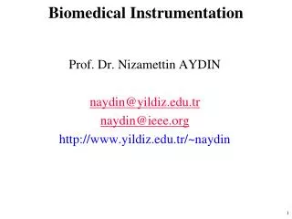
- - - - - - - - - + + + + + + + + + + - + - + - + - + - + - + - + - + - + - + - + - + - + - + - + - + - + - + - + - + - + - + - + - + - + - + - + - + - + - + - + - + - + - + - + - + - + - + - + - - + Transducers produce sound: piezo-electric crystal Applied voltage induces expansion. Dr. Blanton - ENTC 4370 - ULTRASONICS 45
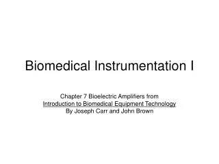
+ + + + + + + + + - - - - - - - - - + - + - + - + - + - + - + - + - + - + - + - + - + - + - + - + - + - + - + - + - pressure + - + - + - + - + - + - + - + - + - + - + - + - + - + - + - + - + - + - + - + - + - Transducers detect sound: piezo-electric crystal Applied pressure induces voltage. Dr. Blanton - ENTC 4370 - ULTRASONICS 46
Piezo-electric crystal properties • Applied voltage induces crystal contraction/expansion. • Contraction/expansion produces pressure pulse. • Applied pressure induces voltage change. • Can be used as both transmitter and receiver. Dr. Blanton - ENTC 4370 - ULTRASONICS 47
electrical pulse electrical pulse Acoustic pulse production high-Q transducer low-Q transducer Dr. Blanton - ENTC 4370 - ULTRASONICS 48
Acoustic pulse production • A medical transducer produces a “characteristic” frequency. • For each electrical impulse, a pulse “train” that consists of N sinusiodal cycles is produced. • The “Q” of a transducer is a measure of the number of cycles in a pulse train. Dr. Blanton - ENTC 4370 - ULTRASONICS 49
High- versus low-Q transducers • High-Q transducers • High intensity • Long-duration pulse “train” • Low-Q transducers • Lower intensity • Shorter-duration pulse train Dr. Blanton - ENTC 4370 - ULTRASONICS 50