Download
1 / 35
350 likes | 369 Views
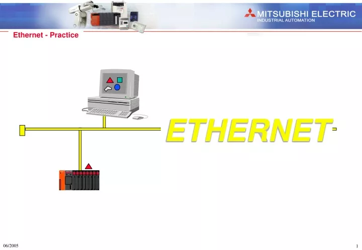
Learn how to configure and test Ethernet communication for PLC devices. Set up IP addresses, ports, and connections between PC and PLC. Practice data transfer and device testing. Detailed step-by-step exercises provided.

E N D
AX80 AX80 AX80 AX80 AY80 AY80 AY80 AY80 A3A CPU A62P ETHERNET
A1SJ71QE71 Exercise 1: GX IEC Dev - Ethernet Communication Terminator: 50 Ohm IP-Address: 192.168.1.100 Subnet Mask 255.255.255.0 • Download Project • Upload Project • Write data to PLC • Read data from PLC • Device test • Read PLC diagnosis GX IEC Developer IP-Address 192.168.1.1 Port-Number 1281 Terminator: 50 Ohm
Exercise 1: Configuration Setup 1.) PC: Configuration - Install PC Ethernet card (Driver) - Set IP-Address for the PC - Set Subnet mask for the IP-Address 2.) PLC: Initial processing (Network parameter) - Set IP-Address 3.) PC - PLC: Connection TEST - Use PING function to test if you can reach the IP-Address of the PLC 4.) PLC: Open Connection - Set one Port for the PC communication 5.) GX IEC Dev: Transfer Setup - Do settings for the PC - Do settings for the PLC
Exercise 1: PC Configuration 1.) Install PC Ethernet card (Driver) 2.) Set IP-Address for the PC192.168.001.100 Set Subnet mask for the IP-Address 255.255.255.000
Exercise 1: Initialization of Ethernet module A-Series sample program : Set IP-Address to: 192.168.001.001 For Details refer to chapter: 5.3.1 Data for Initial Processing (A-Series Manual)
Exercise 1: Initialization of Ethernet module Initialization Parameter for a System-Q PLC : Mode Starting I/O-No. Network-No. Group-No. Stations-No. Write at RUN time IP-Address Initial Timing Do not wait for OPEN Always wait for OPEN Data code Protocol : Online : Set the starting I/O No. (hexadecimal) : Set network No. (1 - 239 decimal) : Set group No. (0 -32 decimal) : Set station No. (1 - 64 decimal) : Enable write at RUN time : Set IP-Address : 192.168.1.1 (decimal) : Communication impossible at STOP time (B1-16) : Communication possible at STOP time (B1-16) : Data exchange in Binary or in ASCII Code : Ethernet (V2.0) - Use this standard !
Exercise 1: Initialization of Ethernet module System Q Initial processing using GX IEC Dev 6 > PLC Parameter > MELSECNET / Ethernet Choose Ethernet as Network type and designate all Settings !
Exercise 1: Initialization of Ethernet module Initialization for a System-Q PLC with GX Developer 8 > Parameter > Network Parameter > MELSECNET / Ethernet Choose Ethernet as Network type and designate all Settings ! First I/O Number of the Ethernet card (0; 10; 20; 30; ...... hexadecimal) ! You can build different virtual networks with the parameter Network No. ! You can build different groups of some PLC‘s in one virtual network ! Every node or PLC needs a station number. Do not set the same station number to different nodes at the same time !
Exercise 1: Initialization of Ethernet module Initialization for a System-Q PLC with GX Developer 8 Ethernet module does not stop communication if PLC CPU changes into STOP mode. Independently of this setting is communication from GX Developer ! Allows to change data in the PLC CPU during RUN mode. Independently on this setting is online change or device test which can be performed from GX Developer !
Exercise 1: Test Initialization Connection test to the Ethernet module with the PING function !
Exercise 1: Open TCP/IP Connection to the PC A Series - Open Connection with GX IEC Developer program Connection Type: TCP/IP Unpassive Open (16#8003) with Port-No. 1281 dec For Details refer to chapter : 5.4.1 Data for Opening (A-Series Manual)
Exercise 1: Open TCP/IP Connection to the PC A Series - Open Connection with GX Developer program Connection Type: TCP/IP Unpassive Open (16#8003) with Port-No. 1281 dec Set Connection Type X19 - Initial normal end Y 8 - Open request X10 - Open normal end Set Port Number Waiting time open request Waiting time open error Reset Open request if the Connection is closed For Details refer to chapter : 5.4.1 Data for Opening (A-Series Manual)
Exercise 1: Open TCP/IP Connection to the PC System Q - Open Connection with GX IEC Developer program Connection Type: TCP/IP Unpassive Open (16#8003) with Port No. 1281 dec
Exercise 1: Open TCP/UDP Connection to the PC System Q - Open Connection with GX Developer Parameter Connection Type: TCP/IP Unpassive Open (16#8003) with Port No. 1281 dec Connection Type: UDP/IP Unpassive Open (16#0101) with Port No. 1282 dec
Exercise 1: Transfer Setup System Q - Ethernet Transfer setup of GX IEC Dev 6 • Online • Transfer setup PC side They have to be different ! PLC Ethernet GX Developer is using Automatic UDP Port 5001 (TCP 5002) for Ethernet transfer !
Exercise 1: Transfer Setup System Q - Ethernet Transfer setup of GX Developer PC Settings PLC Settings Time out Retry times Host Station: The same settings as made for the PLC settings GX Developer is using Automatic UDP Port 5001 for Ethernet transfer !
Exercise 2: GX Configurator-DP Network Download Setting for Ethernet
Exercise 3: Fixed Buffer Communication Data exchange from PLC 1 to PLC 2 ! Receive Send PLC 2 IP-Address 192.168.1.2 PLC 1 IP-Address 192.168.1.1 D30-D39 D30-D39 Buffer 3: Port 1283 Buffer 3: Port 1283 Connection Type: 0002H bit0: 0 = Send bit1: 1 = Existence Check bit7: 0 = no pairing open bit8: 0 = TCP/IP bit9: 0 = with procedure bit15:0 = active open Connection Type: 8003H bit0: 1 = Receive bit1: 1 = Existence Check bit7: 0 = no pairing open bit8: 0 = TCP/IP bit9: 0 = with procedure bit15:1 = unpassive open
Exercise 3: Vorgehensweise PLC 1 und PLC 2 Set Initial parameter 1. Initialization Set Initial request signal Set communication parameter 2. Open Connection Set open request signal Data exchange via Fixed Buffer 3. Data exchange 4. Close Connection Reset open request signal 5. Re-Initialization Reset initial request signal
Exercise 3: Buffer 3 - Send (PLC 1) ConnectionType 16#0002 = Active Open to Send Data ! Rem_IP_Address 16#C0A80102 = 192.168.1.2 Destination IP Address (PLC2) ! No_of_Datawords Size of Data block to be send ! SendData Start device of the Send data block !
Exercise 3: Buffer 3 - Receive (PLC 2) ConnectionType 16#8003 = Unpassive Open to receive Data ! ReadDatawords Size of Data block to be received ! ReadData Start device of the data block where the received data should be stored !
Exercise 3: Buffer 3 (PLC 1 to PLC 2) PLC 1 PLC 2 Buffer 3 Buffer 3
Exercise 4: Fixed Buffer Communication Data exchange between PLC 1 and PLC 2 ! Send Receive Receive Send PLC 1 IP-Address 192.168.1.1 PLC 2 IP-Address 192.168.1.2 D30-D39 D30-D39 Buffer 3: Port 1283 Buffer 3: Port 1283 Buffer 4: Port 1284 Buffer 4: Port 1284 D40-D49 D40-D49 Buffer 3 Connection Type: 0002H bit0: 0 = Send bit1: 1 = existence check bit7: 0 = no pairing open bit8: 0 = TCP/IP bit9: 0 = with procedure bit15:0 = active open Buffer 4 Connection Type: 8003H bit0: 1 = Receive bit1: 1 = existence check bit7: 0 = no pairing open bit8: 0 = TCP/IP bit9: 0 = with procedure bit15:1 = unpassive open Buffer 3 Connection Type: 8003H bit0: 1 = Receive bit1: 1 = existence check bit7: 0 = no pairing open bit8: 0 = TCP/IP bit9: 0 = with procedure bit15:1 = unpassive open Buffer 4 Connection Type: 0002H bit0: 0 = Send bit1: 1 = existence check bit7: 0 = no pairing open bit8: 0 = TCP/IP bit9: 0 = with procedure bit15:0 = active open
Exercise 4: Setup for PLC 1 and PLC 2 Designate Initial parameter 1. Initialization Set Initial Request signal 2. Open processing - Open Buffer 3 + 4 Designate communication parameter Set Open Request signal Fixed Buffer Communication 3. Data exchange 4. Close Connection Reset Open Request signal 5. Re-Initialization Reset Initial Request signal
Exercise 4: Fixed Buffer (PLC 1 / PLC 2) PLC 1 PLC 2 Buffer 3 Buffer 3 Buffer 4 Buffer 4
Exercise 4: Fixed Buffer (PLC 1 / PLC 2 / PLC 3) PLC 1 PLC 2 IP-Address 192.168.1.201 IP-Address 192.168.1.202 Network No. 1 Network No. 1 Station No. 1 Station No. 2 Buffer 1 1281 16#8003 Buffer 1 1281 16#8003 Buffer 2 1282 16#0101 Buffer 2 1282 16#0101 Buffer 3 1283 16#0002 Buffer 3 1283 16#8003 Buffer 4 1284 16#8003 Buffer 4 1284 16#0002 Buffer 5 1285 16#8003 Buffer 5 1285 16#0002 Buffer 6 1286 16#0002 Buffer 6 1286 16#8003 PLC 3 IP-Address 192.168.1.203 Network No. 1 Station No. 3 Buffer 1 1281 16#8003 Buffer 2 1282 16#0101 Buffer 3 1283 16#8003 Buffer 4 1284 16#0002 Buffer 5 1285 16#0002 Buffer 6 1286 16#8003
Exercise 5: File Transfer (FTP Server Function) PC IP:192.168.1.100 PLC 1 IP:192.168.1.1 PLC CPU QE71 File Command Response To Enable FTP functionality: - Initial processing - Activate FTP function - Login and password MS DOS prompt or other FTP Clients For Details refer to chapter: 5.1 File Transfer Functions (QJ71E71 Application Manual)
Exercise 5: Setup for FTP function 1.) PC: Configuration - Install PC Ethernet card (Driver) - Set IP-Address for the PC - Set Subnet mask for the IP-Address 2.) PLC: Initial processing (Network parameter) - Set IP-Address - Activate FTP function - Set login and password Default for System Q > Login: QJ71E71 > Password: QJ71E71 3.) PC - PLC: Connection TEST - Use PING function to test if you can reach the IP-Address of the PLC 4.) MS DOS prompt: - Open FTP Connection - Enter IP-Address - Enter Login name and password
Exercise 5: File Transfer (Initialization / PLC 1) Using GX Developer / Network parameter / Ethernet Default for System Q > Login: QJ71E71 > Password: QJ71E71 For Details refer to chapter: 5.1 File Transfer Functions (QJ71E71 Application Manual)
Exercise 5: File Transfer (Initialization / PLC 1) FTP Function when using GX IEC Developer GX IEC Developer Version 4 and 5 do not have the same PLC Network parameter as the GX Developer so you have to do it with a PLC program and our function blocks ! For Details refer to chapter: 5.1 File Transfer Functions (QJ71E71 Application Manual)
Exercise 5: File Transfer via MS DOS prompt A list of all FTP commands is shown in the manual ! For Details refer to chapter: 5.1 File Transfer Functions (QJ71E71 Application Manual)
dir Status Remote STOP Remote RUN Exercise 5: File Transfer via MS DOS prompt A list of all FTP commands is shown in the manual ! For Details refer to chapter: 5.1 File Transfer Functions (QJ71E71 Application Manual)
dir get delete put Exercise 5: File Transfer via MS DOS prompt A list of all FTP commands is shown in the manual ! For Details refer to chapter: 5.1 File Transfer Functions (QJ71E71 Application Manual)