Download
1 / 10
170 likes | 547 Views
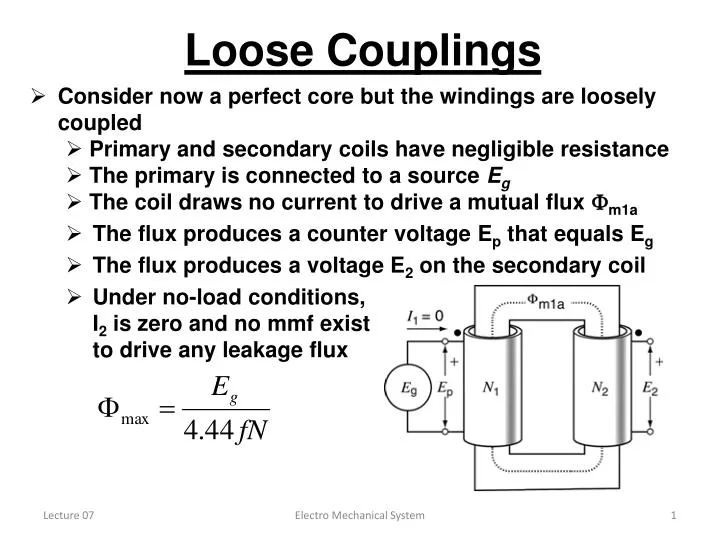
Loose Couplings. Consider now a perfect core but the windings are loosely coupled Primary and secondary coils have negligible resistance The primary is connected to a source E g The coil draws no current to drive a mutual flux m1a

E N D
Loose Couplings • Consider now a perfect core but the windings are loosely coupled • Primary and secondary coils have negligible resistance • The primary is connected to a source Eg • The coil draws no current to drive a mutual flux m1a • The flux produces a counter voltage Ep that equals Eg • The flux produces a voltage E2 on the secondary coil • Under no-load conditions, I2 is zero and no mmf exist to drive any leakage flux Electro Mechanical System
Loose Couplings • Now a load Z is connected across the secondary • currents I1 and I2 immediately begin to flow, and are related by: N1 I1 = N2 I2 • I2 produces an mmf N2I2 and I1produces an mmf N1I1 in the opposite direction • mmf N2I2 forms a flux 2, consisting of a mutually coupled flux m2 and a leakage flux f2 • mmf N1I1 forms a flux 1 , consisting of a mutually coupled flux m1 and a leakage flux f1 • The new mmf’s upset m1a • balance • We combine m1 & m2into • mutual flux m • E2 = 4.44fN2 m • E1 = 4.44fN1 m Electro Mechanical System
Loose Couplings • The new mmf’s upset m1a balance • resolving the modeling conflicts • combine m1 and m2 into a single mutual flux m • Es consists of two parts: E2(N2 m) and Ef2(N2 f2) • They are given by: Ef2 = 4.44fN2 f2 : E2 = 4.44fN2 m • Ep consists of two parts: E1(N1 m) and Ef1(N1 f1) • They are given by: Ef1 = 4.44fN1 f1 : E1 = 4.44fN1 m Electro Mechanical System
Leakage Reactance • The four induced voltages can be rearranged in the transformer circuit as shown above • The rearrangement does not change the induced voltages. • Ef2is a voltage drop across a reactance • Xf2 = Ef2/I2 • Ef1is a voltage drop across a reactance • Xf1 = Ef1/I1 • Home Work: Page 201 Example 10-2 Electro Mechanical System
Equivalent Circuit • Primary and secondary windings are composed of copper or aluminum conductors. • conductors exhibit resistance to the current flow. • the leakage reactance can also be modeled as a series inductance. • Core excitation and losses are modeled as a shunt circuit. • Combining all elements with the ideal transformer forms an equivalent circuit for practical transformers. Electro Mechanical System
Terminal Markings & Taps • Polarity can be shown by means of dots • H1 & H2 for High voltage and X1 & X2 by low voltage • additive polarity when H1 is diagonally opposite to X1 • subtractive polarity when H1 is adjacent to X1 • Voltage drops in lines can be regulated by • Adding taps in the distribution transformer • 2400V/120V transformer can be connected to a line with voltage never higher than 2000V Electro Mechanical System
Losses • As in all machines, a transformer has losses • I2R losses in the primary and secondary windings • Hysteresis losses and eddy-current losses in the core • Stray losses due to primary and secondary leakage fluxes • Losses appear in the form of heat. • Heat produces an increase in temperature. • Drop in efficiency. • Iron losses depend on the mutual flux and hence the applied voltage. • The winding losses depend on the current drawn by the load. Electro Mechanical System
Losses • We must set limits to applied voltage and current drawn by the load • These limits determine the nominal voltage Enp and nominal current Inp of transformer winding (primary or secondary) • Power rating is equal to product of the nominal voltage times nominal current. • Result is not in watts because phase angle can have any value. • The result is expressed in voltampre (VA), in kilovoltampre (kVA) or in megavoltampre(MVA). Electro Mechanical System
Example • The nameplate of a distribution transformer indicates 250 kVA, 60 Hz, 4160 V primary, 480 V secondary; • Calculate the nominal primary and secondary currents • If we apply 2000V to the 4160V primary, can we still draw 250kVA from the transformer? • a) Nominal current of 4160 V winding is • Inp = nominal S/nominal Ep = Sn/Enp • Inp = (250 x 1000)/4160 = 60A • Nominal current of 480 V winding is • Ins = nominal S/nominal ES = Sn/Ens • Ins = (250 x 1000)/480 = 521A Electro Mechanical System
Example b) If we apply 2000 V to the primary, the flux and iron losses will be lower and core will be cooler. The current should not exceed the nominal value, otherwise the winding will overheat. S = 2000 V x 60 A = 120 kVA Electro Mechanical System