Download
1 / 25
250 likes | 388 Views
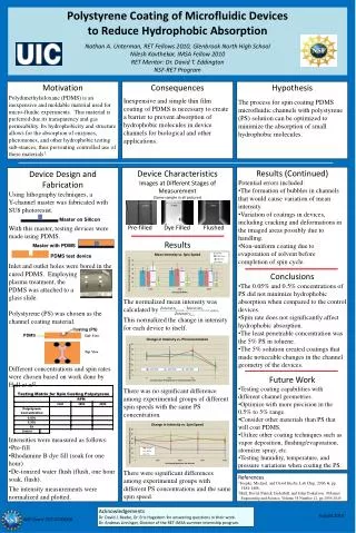
EFI Subsystem Design, Fabrication, and Test Status. Assembly and Test To-Date. ETUs AXB (1 unit): assembled March ’04; RT and TVAC deploy tested, March ’04; redesigned, rebuilt, redeployed April ’04; Sensor redesign, May ’04; Straightness, May ’04; Horiz. Deploy (length cal), June ’04.

E N D
Assembly and Test To-Date • ETUs • AXB (1 unit): assembled March ’04; RT and TVAC deploy tested, March ’04; redesigned, rebuilt, redeployed April ’04; Sensor redesign, May ’04; Straightness, May ’04; Horiz. Deploy (length cal), June ’04. • SPB (1 unit): assembled April ’04; Housing, Door, and Door Actuator redesigned and rebuilt May ’04; vibe’d June ’04; TVAC and RT Deploy, June ’04. • Preamp Enclosure: Four ETUs built, April, ’04 and integrated into ETU Cables, SPB, and AXB; Cable termination redesigned, May ’04 (post-I-CDR); revised ETUs to be built June ’04. • Cables: One Prototype, two ETU Sensor Cables, and one special Thermal Cable fabricated March 29 – April 9, ’04; integrated with ETU Preamp PWBs and ETU SPB and AXB for vibe testing, and Preamp Thermal Model Simulator.
Assembly and Test To-Date • ETUs (con’t) • Preamp PWB: Two ETU Preamp PWB assembled April 9 ’04; integrated with ETU Preamp PWBs and ETU SPB and AXB for vibe testing. One Flight-like PWB assembled for Preamp Thermal Modeling (nominal operation at –130 C!). • BEB: One ETU built, Mar ’04; functional testing, Mar-Apr ’04, design qualified, meets required specifications; Integrated BEB-Preamp-Cable testing ongoing, June ’04. • DFB: One BB ETU with core FPGA functionality (CDI interpreter, waveform filters and filter banks) completed mid-May ’04; successfully integrated with BEB, DCB, and EFI/BEB EGSE, mid-May ’04; true ETU fab and assy late June-early July ’04.
Assembly and Test To-Date • GSE and Harnessing • EGSE: BEB/EFI Electrical GSE complete and characterized, April ’04; spare unit with reduced fuctionality to support BEB Flight Board Testing, on-order, June ’04. • Faraday Boxes: two Faraday boxes with internal fixtures and wiring (signal paths and Plasma Simulators), complete, June ’04. • MGSE: AXB TVAC fixtures done; AXB FrangiBolt simulator done; AXB HDeploy Track, TBC, June ’04; SPB TVAC Takeup Reels, TBC, June ’04 for SPB TVAC; SPB TVAC Fine Wire Deploy Reels, TBC, June ’04. • TVAC Harnessing: design complete, April-May ’04; SPB ETU built, May ’04; AXB to be built, July ’04. • ETU Harnessing: design complete, May ’04; under fabrication to support II&T, June ’04. • Misc. Test Harnessing: dual boom unit Y-Test Harness, built May ’04. Breakout boxes, etc., designed and built as needed.
Near-Term Testing • Mechanical • AXB and SPB Vibe (June 9 and 10) – units passed. • SPB TVAC (Deploy Testing) (June 18-25; pending completion of B20 “Bayside” refurbishment), AXB TVAC complete and successful. • AXB and SPB Deploy Calibrations (late June). • Testing required to support FLT machining orders complete. • Thermal • Long-Eclipse Thermal Simulation and Thermal Shock (aka. L-N2 Dunk) for Preamp, -130 C to 60 C (May 2004; July 2004) • Electrical • Integrated electrical testing of EFI and BEB (all of June 2004; EFI/BEB EGSE complete; Faraday Boxes complete in late April). • Formal Preamp Thermal Qualification (TVAC cycles and DPA) (Jul-Aug 2004, parallel with F1 FLT build). • Suite-Level Testing (II&T) • EFI ETU delivered to II&T July 2004.
Parts Procurement, Qual, and Contamination • Long-Lead Items • All long-lead items in-house or on schedule for delivery to support July ’04 start of Flight production. • Custom Cable • SPB Flight motors, bearings, slip rings, machine parts. • AXB Flight stacers, bearings. • Preamp Enclosure machine parts and Cable Fab fixtures. • BEB parts kits. • DFB parts kits. • Preamp parts kits. • Qualification Testing • All parts passed radiation (AD5544 DAC and LTC1604 ADC, in particular). • Formal qualification of Preamp OP-15 and design via TVAC and DPA in parallel to ETU and Initial Flight Build (July ’04). • Contamination • All suspect parts sent to UCLA for magnetic characterization (eg. SPB motors and geartrain).
Facilities • ETU Testing • Refurbished UCBSSL Silver B20 “Bayside” TVAC Chamber • Accommodates up to 4 SPB. • UCBSSL Addition High Bay “Geoffrey” TVAC Chamber • Accommodates fully-deployed AXB vertically. • Vibe Testing done off-site. • AXB Horizontal Deploy Track. • SPB Vertical Deploy Fixtures in High Bay • Alternately, Std. Horizontal Deploy in SSL “Dungeon”. • FLT Testing • Same facilities as ETU, plus: • New UCBSSL Silver B20 “EFI Snout” TVAC Chamber • Accommodates fully-deployed AXB horizontally. • Vibe testing done off-site.
Calibration and Test • Mechanical and Electro-Mechanical • SPB Deploy Length • Turns Count • Deploy Rate • SPB Door Actuation and Function • AXB Deploy Length • Repeatability • Stiffness and Straightness • SPB Door SMA and AXB Deploy FrangiBolt Currents • SPB and AXB Cable Continuity and Isolation during Deploy • Electrical • EFI/BEB Calibration • Quiescent and Operational Currents • DC Functional Tests (Gain, Offset, CMRR, Linearity, 0.1% Matching) • AC Functional Tests (Transfer Function, CMRR, Slew Rate, Linearity) • EFI/SCM/FGM via DFB Phase Intercalibration • See Suite-Level I&T.
Assembly and Test Flow SPB Assembly and Test Flow, based on ETU Experience:
Instrument (Suite) I&T Plan • Integration and Test • Instrument I&T takes place at UCBSSL. • Environmental (TVAC, Vibe, Suite EMC as per THM-SYS-005 Environmental Verification Spec). • Limited and Comprehensive Performance Testing: • SPB Motor Simulators (aka. Motor-in-a-Box) and AXB Test FrangiBolts (aka. FrangiBolt-in-a-Box) used for pre- and post-environmental functional tests of deploy mechanisms, as well as dummy electrical loads during “fake” TVAC deploy testing. • Internal DC and AC functional test capability used for pre- and post-environmental functional tests of sensors; sensors may be directly stimulated via ACTEST line on Test/Enable plug. • End-to-End SPB and AXB TVAC Deploy Testing (IDPU-controlled; Motor-in-a-Box and FrangiBolt-in-a-Box). • Integrated Fields System (DCB, DFB, EFI, SCM, FGM) modes testing: Nominal, Slow, Fast, Torturous Data Exchange, and “Mode X”. • Phase intercalibration between EFI, SCM, and FGM performed using EFI Test/Enable Plugs, SCM Mu-Metal Box, FGM TCU and 12-channel, 16-bit, +/- 10-V National Instruments DAC system.
S/C (Probe) I&T Plan • Integration and Test • Probe I&T takes place at Swales Aerospace. • Environmental (TVAC, Vibe, Shock, EMI; as per THM-SYS-005 Environmental Verification Spec). • Limited and Comprehensive Performance Testing: • Sensors via internal DC and AC Functional Test capability, monitored through ITOS. • Actuators via external Boom Loads Simulator (BLS) and Test/Enable plugs, monitored through ITOS. • Sensors may be stimulated externally via breakout on BLS, if required (non-standard test). • Initial ITOS requirements outlined, Apr 2004. • Red/Green tag items: • One red tag Snout Cover per SPB (4 total). • One red/green Test/Enable plug per SPB (4 total). • One red tag Tube Cover per AXB (2 total). • One red/green Test/Enable plug supporting both AXBs (1 total)
F1-F2 Production Schedule SPB Cables Vibe TVAC, RT Preamp 13 Sep ‘04 AXB 5 Jul ‘04 BEB Cals 4 Oct ‘04 26 Jul ‘04
FLT Production Schedule • Grassroots estimate, based on ETU experience (1 person-day/subassy, TVAC and RT testing experience, electrical checkout, etc.). • Subassembly Assy tasks (eg. SPB Motor, Spool, etc.) carry 100% margin. • Rate setting steps are Mechanical Test and BEB Board Test (3-week durations). • 3-week delivery cadence, with 2-week overlap between Fn Boom Assy and Fn+1 Subassembly Assy work. • 5-week delivery cadence removes all overlap between successive Boom and Subassembly Assy work. • Downstream schedule risk will be reduced by using Subassembly schedule margin and larger summer labor pool (F1) (GSRs) to lay in overstock for F2 through F6. • Dedicated TVAC personnel (Jelinsky, McKee, Marker) used to reduce schedule risk from spreading Engineering staff thinly between Assembly, Test, and I&T.
Deploy and Commissioning • Draft Deploy and Commissioning plan developed Nov 2003. • Draft plan refined Mar 2004 in response to revised launch date (21 Aug -> 21 Oct 2006). • EFI SOH to be determined on all probes using stowed DC and AC functional test capability during initial on-orbit check-out. • Instrument SOH used to determine probe assignment. • EFI deployed on all probes after placement in initial science orbits. • EFI deployed in 6 to 7 steps: • 5 to 6 intermediate deploy lengths with spin up for SPB. • 1 step to deploy both AXB. • Primary constraints on deploy and commissioning: • 1 30-minute TM contact per 3-1/2 hours (thermal). • Desire to gather science data at intermediate deploy lengths and in different plasma regimes.
Deploy and Commissioning • Deploy cycle on single probe (each step >= 3-1/2 hours): • Deploy SPB-X, wait for transmitter to cool down, run Slow Sweep if desired, take Diagnostic Mode data if desired. • Deploy SPB-Y, wait for transmitter to cool down, run Slow Sweep if desired, take Diagnostic Mode data if desired. • Spin Up to desired spin rate for beginning of next deploy cycle. • Slow Sweep: 4 BRAID, 3 USHER, 3 GUARD and 32 BIAS settings; 1152 steps, 1 step/spin, approx. 1 hour duration, data rate TBD (baseline is Diagnostic Mode, which may be overkill). • Diagnostic Mode data: • 2 or 3 DCE channels at 32 samp/s (3.75 deg/samp). • 4 to 6 V channels at 8 samp/s (few mm spatial resolution). • 1536 to 2304 bps; supported out to P1 Apogee for Real-Time contacts.
Deploy and Commissioning • P3 and P4 deploy first: • 2-day, 2-orbit cycle: P3 deploying one orbit, P4 quiescent, then swap. • Full deploy and commissioning takes 14 days. • P1 and P2 deploy next: • P2 on 2-day, 1-orbit cycle: deploy on outbound, quiescent on inbound; 14 days total. • P1 on 4-day, 1-orbit cycle: deploy on outbound, quiescent on inbound; 28 days total. • P1 deploy cycle maybe accelerated depending upon experience gained and data gathered during P3 and P4 deploy and commissioning. • P5 deploys last: • 1 or 2-day cycle, with full deploy and commissioning taking 7-14 days.
Deploy and Commissioning Nominal Deploy and Commissioning Schedule
Operations and Data Validation • Operations • Slow Sweeps and diagnostic data taken several times per year, upon first entry into a new plasma regime, and after long-duration eclipses to maintain optimal bias settings and monitor EFI state-of-health. • EFI instrument mode set by ~30 registers on BEB; a typical mode will be specified with ~200 commands, valid over a typical one month period, once deploy and commissioning are completed. • Data Validation • Both sphere potentials and differential E-field data gathered in all waveform modes, allowing for initial verification of E-field data. • Intercomparison of Eperp and –VxB from ESA and FGM to establish offsets and boom shorting effects.
Operation and Data Validation • Data Rates (can change on-orbit; DFB mode commands) • Slow Survey • Spin-fit radial and spin-avg’d axial E-fields; spin-avg’d SC potential (via ptcls). • Filter Bank of one axis. • Fast Survey • 3 E-field at 32 S/spin; 2-3 sphere potentials at 8 S/spin. • Filter Banks of Standard or Derived quantities. • Particle Burst • 3 E-field at 128 S/s; 2-3 sphere potentials at 32 S/s. • Filter Banks as in Fast Survey. • Wave Burst • 3 E-field at 1024 or 4096 S/s; 2-3 sphere potentials at 256 or 1024 S/s. • Filter Banks as in Fast Survey. • Diagnostic Mode • 3 E-field at 32 S/s; 6 sensor potentials at 8 S/s.
Operations and Data Validation • Nominal Sensor Biasing (CPS and PSBL; Prediction): SC Potential <20 V and stable for CPS-PSBL plasma regimes When sensors run at 20 nA/sensor; Rsheath approx. 50 Mohm. CPS PSBL