Download

1 / 42
420 likes | 654 Views
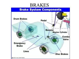
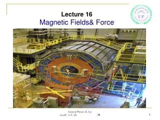
16. Magnetic brakes. ” When a strong magnet falls down a non ferromagnetic metal tube, it will experience a retarding force . Investigate the phenomenon . ”. Outline. Qualitative explanation. Quantitaive explanation Force modeling Dipole case Equation of motion.

E N D
16. Magnetic brakes ”When a strong magnet falls down a nonferromagnetic metaltube, it will experience a retarding force. Investigate the phenomenon.”
Outline Qualitative explanation • Quantitaive explanation • Force modeling • Dipole case • Equation of motion • Apparatus and experimental methods • Measurement of magnetic flux change • Measurement of magnet velocity • Comparison of experimental data and theory • Dependence of terminal velocity on magnet size • Terminal velocity for dipole • Dependence of terminal velocity on material conductivity • Equation of motion
What causes the force? • Magnet falls down under the influence of gravity • Magnetic flux is changing in space • Current is induced in the tube • Currents act on magnet by force thatreduces the speed of magnetic fluxchange (reducing the magnet speed) z Direction of induced currents In the middle there is no induced current – magnetic moment velocity of a magnet
Force • According to Newton III. law: • Because we know what is the force on a current loop we can write z F B Bz B Bz G Bρ Fρ(Bz) Fρ (Bz) Bρ Fz (Bρ) Fz (Bρ) Assumption: no skin effect ρm force on magnet force on current tickness of the tube dz – lenght of a loop mean radius of the pipe ∆ρ Cu;
Force • Magnetic field component is causing the force in direction so the force can be written as Bz Bz Using Maxwell equation we derive expresion for Bρ Bρ z Fρ(Bz) Fρ (Bz) Fz (Bρ) Fz (Bρ) change of magnetic flux in z direction ε – induced voltage σ– material conductivity R – restistance of the ring
Force • After rearranging the term we obtain total force on a magnet caused by induced current z1, z2 – coordinates of the tube edges
Equation of motion • II. Newton law for magnet states • After solving for we obtain () Substitution: • Function is in form of exponential decay • Terminal velocity can be expressed as
Screw for vertical dislacement (0.01 mm) Determing magnetic flux change Stand Magnet Coil same diameter as tube Wooden cube (in place to eliminate magnets impact on the scale) • Because can be difficult to calculate we decided to experimentaly determine it Scale Measured by scale Adjusted on current source I = 1A (DC) Property of coil N = 40
Plastic tube Adjustable stand Coil Neodimium magnets Brass screw Scale Current source Wooden block
Example of obtained data - magnetic flux change 2r = 4 mm h
Velocity measurement Coil used for releasing magnet Coil used for releasing magnet Computer controlled power supply Detector coils PC Detector coils ADC
Velocity measurement – coils detectpassing magnet due to induction: 2r = 4 mm h Copper3 solenoids
Dependence of terminal velocity on cylindrical magnets height – Cu and Al Theoretical values numericaly calculated from: 4 mm h Substitution:
Dipole • Dipole magnetic field in z direction (measured from the magnet): • If the magnet is far enough from the edges of the tube wecan write
Terminal velocity - dipole • Spherical magnet – radius 2.5 mm • Aluminium tube d – magnet’s density r – radius of a magnet vt – theoretical velocity
Velocity - conductivity • Copper tube coled down to 77K in insulating box with liquid N2 • As tube warms up magnet is releasedand velocity measured • Magnet was constantly kept on liquid nitrogen temperature ≈ 77K (constant magnetization ) • Conductivity measured directly - resistance of wire attached to tube Insulating box Coil used for releasing magnet Detector coils Copper wire
Dependence of velocity on distance traveled • Theoretical values • calculated numericaly from • Initial speed determined experimentally • System of cylindrical magnet ( ) and weight • Velocity experimentaly determined by using relation
Conclusion • Theoretical model developed • Quantitaive • No free parameters • Very good correlation with experiment • Assumptions • No skin effect • Constant direction and magnitude of magnetization of magnet • Rotational symmetry of the tube • Experiment • Parameters changed • Size and shape of magnet • Conductivity of material
Reference • Valery S Cherkassky, Boris A Knyazev, Igor A Kotelnikov, Alexander A Tyutm; Eur. J. Phys.; Breaking of magnetic dipole moving through whole and cut conducting pipes • Edward M. Purcell; Electricity and Magnetism Berkley physics course – volume 2, Second Edition; McGraw-Hill book company
Magnetic brakes Croatian team Domagoj Pluscec IYPT 2014 team of Croatia Thank you Reporter: Domagoj Pluščec
Current v – magnets speed time change of magnetic flux ε – induced voltage σ– material conductivity l – ring perimeter A – area of ring cross section R – restistance of the ring - magnets position - can be expresed as space change because magnetic flux around the magnet doesn’t depend on time
Determing Bρ • Maxwell equation (magnetic field lines are closed curves) 2 3 1 – magnetic flux Schematic representation of the magnetic flux through a closed surface (discshape)
Terminal velocity • Terminal velocity is reached when gravitational force is equal to magnetic force Supstitution
Assumptions used in derivation of model • Tube is rotational symetrical in z direction • Thin tube and the magnet is falling with low velocities(model does not take into consideration skin effect) • We didn’t take into account case in which magnet rotates in such a way that direction of its magnetic moment changes Cu; – skin depth – characteristic frequency
Detailed dipole model derivation 1/2 • In theoretical modeling part we obtained in this equation we need to find for dipole • Magnetic flux trought cross section of tube can be expressed as • And by using expresion for a field of dipole in z direction we obtain magnetic flux in z direction
Detailed dipole model derivation 2/2 • Magnetic flux in z direction • From that we derive magnetic flux change • By knowing magnetic flux change we can obtain force • If the magnet is far enough from the edges of the tube we can write
Equation of motion with initial velocity After solving for we obtain: Supstitution:
Terminal velocity derived from energy conservation After substituing terms for current and resistance we obtain Supstitution
Apparatus properties - magnets • Neodimium magnets • Magnetic permeability • Density • Cylindrical magnets • Spherical magnets
Determing magnetic flux change 3 Function k(a) aproximated by on interval [2.81, 27.8] mm
Velocity measurement • Coils detectpassing magnet due to induction: Aluminium, 2 solenoids
Theoretical change of velocity Supstitution:
Cooling - change of the magnetization of the magnet For our case:
Cooling - change of tube dimesion • Change of radius of the pipe
Tube with slit vs tube without slit • 1 m long aluminium tube • Magnet properties • Cylindrical magnet