Download
1 / 123
1.43k likes | 2.13k Views
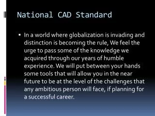
Revitizing the U.S. National CAD Standard. Mathew Miller BIM/CAD systems Manager. Mathew Miller. BIM/CAD Systems Manager with SMPC Architects 17 years experience in the production of construction drawings Associates of Applied Architecture from Denver Institute of Technology

E N D
Revitizing the U.S. National CAD Standard Mathew Miller BIM/CAD systems Manager
Mathew Miller • BIM/CAD Systems Manager with SMPC Architects • 17 years experience in the production of construction drawings • Associates of Applied Architecture from Denver Institute of Technology • Bachelor of Arts and Master of Architecture from University of New Mexico • Chair of NCS UDS Modules Task Team for the NCS • One of the Leaders of 505 BIM Users Group Presenter
Rick Green, FCSI, CCS, CCCA, AIA, LEED AP, NCARB, SCIP Ed Lowe, CSI • Architect with Wilson & Company, Inc. in Albuquerque, NM • B.S., Master of Architecture, University of Michigan • Co-author, The Architect’s Guide to the U.S. National CAD Standard • NCS Project Committee Steering Committee, NCS Project Committee, Past Chair of UDS Program Task Team / UDS Modules Task Team • CAD Coordinator with Burgess & Niple, Inc. in Painesville, OH • 25 years experience in the production of construction drawings • Use and support of AutoCAD for the past 16 years • NCS Project Committee Steering Committee, NCS Project Committee, Past Chair of CAD Layers Task Team, Chair UDS Program Task Team for CSI Contributors
Revitizing the U.S. National CAD Standard Mathew Miller BIM/CAD systems Manager Episode two
Learning Objectives Upon completing this program, participants should know how to: • Configure Revit to include NCS formats such as line widths, annotations, line styles, object styles, symbols, tags, etc. • Identify the relationship between Building Information Modeling (BIM) and the NCS • Modify Revit default settings for keynotes to comply with NCS notation requirements. • Define NCS compliant symbols and tags. • Create NCS compliant family libraries. • Will understand how Revit is effected by the different parts of the NCS.
Who is Here? • Facility Managers / Owners • CAD Managers / CAD Coordinators • Revit Power Users just trying to get a head
Wilson Company, Inc., Engineers & Architects What is the Relationship Between BIM and the NCS?
National BIM Standard (NBIMS) Developed by the NBIMS Project Committee (committee of the NIBS Facility Information Council) Defines a minimum BIM Defines the scope of BIM Provides guidance to those currently establishing BIMs Vendor neutral
National BIM Standard (NBIMS) NBIMS: The NCS "plays a crucial role in easing the transition to new BIM software systems and the 3-D object-based standards"
National BIM Standard (NBIMS) Graphical Information: “Since all drawings should at this point be National CAD Standard compliant we are making this a requirement for a minimum BIM.”
What is the NCS ? The NCS establishes standards for organizing and presenting drawing information for: • Facility Planning • Design • Construction • Facility Operation
Why was the NCS Created? • Too many standards and lack of coordination • Largely driven by Federal agencies and industry organizations on behalf of their membership • Focus on “facility cycle” rather than “my cycle”
What does the NCS do? The NCS provides uniformity for graphical information on drawings, just as CSI’s MasterFormat, SectionFormat, and PageFormat provide uniformity for textual information in the project manual.
NCS Components – NCS v4.0 Introduction and Appendices; and Plotting Guidelines (maintained by the NCS Project Committee) CAD Layer Guidelines Modules 01 - 08 of CSI’s Uniform Drawing System
NCS and Revit • Revit is a BIM oriented program that collects building information • The NCS is a standard for displaying building information.
The 10 parts of the NCS • Part 1 AIA CAD Layer Guidelines • Part 2 Drawing Set Organization • Part 3 Sheet Organization • Part 4 Schedules • Part 5 Drafting Conventions • Part 6 Terms and Abbreviations • Part 7 Symbols • Part 8 Notations • Part 9 Code Conventions • Part 10 Plotting Guidelines
The 10 parts of the NCS • Part 5 Drafting Conventions • Part 8 Notations • Part 7 Symbols • Part 4 Schedules • Part 3 Sheet Organization • Part 2 Drawing Set Organization • Part 10 Plotting Guidelines • Part 1 AIA CAD Layer Guidelines • Part 9 Code Conventions
The 10 parts of the NCS • Part1 AIA CAD Layer Guidelines • Part 2 Drawing Set Organization • Part 3 Sheet Organization • Part 4 Schedules • Part 5 Drafting Conventions • Part 6 Terms and Abbreviations • Part 7 Symbols • Part 8 Notations • Part 9 Code Conventions • Part 10 Plotting Guidelines
M O D U L E 04 14.97 UDS Drafting Conventions
M O D U L E 04 UDS Use of Line Widths LINE WIDTHS MATCH ISO 128-20-1996
Line Width Technical pens have a very long history. With the advent of CAD everything changed. Historic Reference NCS4
Line Width • Revit allows 16 different line weights. • Change the first 9 to match the NCS4. • Leave the remaining 7 in the Revit out of box condition. P P P P P P P Revit Out the box
The 10 parts of the NCS • Part1 AIA CAD Layer Guidelines • Part 2 Drawing Set Organization • Part 3 Sheet Organization • Part 4 Schedules • Part 5 Drafting Conventions • Part 6 Terms and Abbreviations • Part 7 Symbols • Part 8 Notations • Part 9 Code Conventions • Part 10 Plotting Guidelines
Notations Module M O D U L E 07 UDS Provides: • Notation formats • Requirements for the creation and use of notes • Standard for note locations
M O D U L E 07 UDS Text Format Decision time • Choose your font wisely. • NCS requires: “Fonts should be capitalized, proportional, sans-serif, and non-stylized. Do not use italics, underlining, bold, or other highlighting techniques.” – NCS page UDS-07.20. COOL LOOKING TEXT 123 BOLD LOOKING TEXT 123 SERIF STYLE TEXT 123 ITALIC LOOKING TEXT 123 SIMPLEX.TTF TEXT 123 ROMANS.TTF TEXT 123 ROMAND.TTF TEXT 123 SANSERIF.TTF TEXT 123 CALIBRI.TTF TEXT 123 TAHOMA.TTF TEXT 123 ARIAL.TTF TEXT 123
Graphic Conventions for Text and Notes • On page UDS-04.34 of the NCS it states “The minimum text size is 3.2 mm (1/8") for hand drafting and 2.5 mm (3/32") for CAD. Smaller text size is generally not legible on reduced or one-half size sets. The use of bold, italic, and underline should not be used for notes. • All text on drawings should be CAPITILIZED • Most symbols defined in the symbols module of the NCS are defined by the 3/32” text.
M O D U L E 07 14.97 UDS Dimensions • If you use the slash as a terminator the NCS does not specify the exact length to use. • Does not specify stacked fractions. • Does not specify if you should suppress 0’. • These are items you will have to decide for yourself.
M O D U L E 07 UDS Notation Types 5 TYPES OF NOTES: • General Notes • General [Discipline] Notes • General Sheet Notes • Reference Keynotes • Sheet Keynotes
M O D U L E 07 REFERENCE KEYNOTES GENERAL SHEET NOTES 1. IIII II III III 2. II III II II 3. II IIIII II III 4. I II IIII III I 5. III I II IIII I 1. IIIII.I III XX 2. IIIII.I II II X 3. IIIII.I I II IIII 4. IIIII.I II IIIIII 5. IIIII.I IIII IIIX SHEET KEYNOTES 1.III III IIII II 2.III III II II 3. III II UDS Notation Hierarchy in the Note Block General Notes General Discipline Notes General Sheet Notes Reference Keynotes Sheet Keynotes
M O D U L E 07 UDS General Sheet Notes • Apply only to the sheet on which they appear • Do not correspond to a graphic representation • Used to communicate sheet specific information or instructions. • Are not directly “linked’ to other sheets or specifications • May be located on any sheet in the drawing set
M O D U L E 07 UDS General Sheet Notes Example: “DIMENSIONS DRAWN TO PARTITION WALLS ARE TO FACE OF STUD UNLESS NOTED OTHERWISE.”
M O D U L E 07 UDS Reference Keynotes • Used to identify graphic representations of items and directly reference them to specific specification sections • Are located within the Graphic and Notation Area of a Drawing Block • Are connected to the graphic by a leader and an identifier
M O D U L E 07 UDS Reference Keynotes Root - use same specification number that references item 0 3 2 0 0 0 . A 0 1 Root format coordinates with MasterFormat™ 2004
M O D U L E 07 UDS Reference Keynotes Modifier- optional, user- defined, two- digit number 0 3 2 0 0 0 . A 0 1
M O D U L E 07 03 30 00.A 03 20 00.B 03 20 00.A (#4 BARS) UDS Appearance of Reference Keynotes in the Drawing Area REFERENCE KEYNOTES DIVISION 03 - CONCRETE 03 20 00.A REINFORCING STEEL 03 20 00.B WELDED WIRE MESH 03 30 00.A CAST-IN-PLACE CONCRETE Reference Keynotes in Note Block Reference Keynotes in Drawing Block
M O D U L E 07 UDS Reference Keynotes Decision time 0 0 0 0 0 0 2 x 2 x 2 0 0 0 0 0 0 2 x 4 0 0 0 0 0 0 6
M O D U L E 07 UDS Sheet Keynotes • Identify graphic representations of items that are not referenced or linked back to the specifications. • Are noted within the Graphic and Notation Area • of a Drawing Block. • Are connected to an item with a leader and a hexagonal symbol containing a numeric indicator
M O D U L E 07 2 UDS Appearance of Sheet Keynotes in the Drawing Area SHEET KEYNOTES 1. EXISTING FLOOR DRAIN 2. DASHED LINE INDICATES SOFFIT ABOVE Sheet Keynotes in Note Block Sheet Keynotes in Drawing Block
Notations - Revit Keynotes • Revit’s keynote system can do both Reference Keynotes and Sheet Keynotes it seems built more around the Reference keynotes.
09 2400.B 05 4000.B