Download
1 / 22
220 likes | 467 Views
Lecture 1: Introduction, Embedded Systems, Product Life-Cycle, ARM Programming. EE 319K Introduction to Microcontrollers. Agenda. Course Description Book, Labs, Equipment Grading Criteria Expectations/Responsibilities Prerequisites Embedded Systems Microcontrollers Product Life Cycle

E N D
Bard, Gerstlauer, Valvano, Yerraballi Lecture 1: Introduction, Embedded Systems, Product Life-Cycle, ARM Programming EE 319KIntroduction to Microcontrollers
Bard, Gerstlauer, Valvano, Yerraballi Agenda • Course Description • Book, Labs, Equipment • Grading Criteria • Expectations/Responsibilities • Prerequisites • Embedded Systems • Microcontrollers • Product Life Cycle • Analysis, Design, Implementation, Testing • Flowcharts, Data-Flow and Call Graphs • ARM Architecture • Programming • Integrated Development Environment (IDE)
Bard, Gerstlauer, Valvano, Yerraballi EE306 Recap: Digital Logic Positive logic: Negative logic : True is higher voltage True is lower voltage False is lower voltage False is higher voltage • AND, OR, NOT • Flip flops • Registers
Bard, Gerstlauer, Valvano, Yerraballi EE302 Recap: Ohm’s Law V = I * R Voltage = Current * Resistance I = V / R Current = Voltage / Resistance R = V / I Resistance = Voltage / Current • P = V * I Power = Voltage * Current • P = V2 / R Power = Voltage2/ Resistance • P = I2 * R Power = Current2 * Resistance
Bard, Gerstlauer, Valvano, Yerraballi Embedded System • Embedded Systems are everywhere • Ubiquitous, invisible • Hidden (computer inside) • Dedicated purpose • MicroProcessor • Intel: 4004, ..8080,.. x86 • Motorola: 6800, .. 6812,.. PowerPC • ARM, DEC, SPARC, MIPS, PowerPC, Natl. Semi.,… • MicroController • Processor+Memory+I/O Ports (Interfaces)
Bard, Gerstlauer, Valvano, Yerraballi Embedded Systems • A reactivesystem continuously • accepts inputs • performs calculations • generates outputs • A real time system • Specifies an upper bound on the time required to perform the input/calculation/output in reaction to external events
Bard, Gerstlauer, Valvano, Yerraballi Microcontroller • Processor – Instruction Set • CISC vs. RISC • Memory • Non-Volatile • ROM • EPROM, EEPROM, Flash • Volatile • RAM (DRAM, SRAM) • Interfaces • H/W: Ports • S/W: Device Driver • Parallel, Serial, Analog, Time • I/O • Memory-mapped vs. I/O mapped
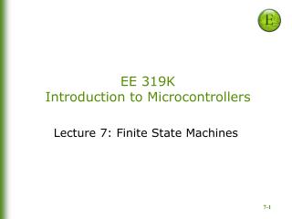
Bard, Gerstlauer, Valvano, Yerraballi Texas Instruments TM4C123 • ARM Cortex-M4 • + 256K EEPROM+ 32K RAM • + JTAG • + Ports • + SysTick • + ADC • + UART
Bard, Gerstlauer, Valvano, Yerraballi Analysis (What?) Requirements -> Specifications Design (How?) High-Level: Block Diagrams Engineering: Algorithms, Data Structures, Interfacing Implementation(Real) Hardware, Software Testing (Works?) Validation:Correctness Performance: Efficiency Maintenance (Improve) Product Life Cycle
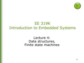
Bard, Gerstlauer, Valvano, Yerraballi Data Flow Graph Lab 8: Position Measurement System
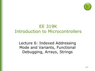
Bard, Gerstlauer, Valvano, Yerraballi Call Flow Graph Position Measurement System
Bard, Gerstlauer, Valvano, Yerraballi Structured Programming • Common Constructs (as Flowcharts)
Bard, Gerstlauer, Valvano, Yerraballi Flowchart • Toaster oven: Coding in assembly and/or high-level language (C)
Bard, Gerstlauer, Valvano, Yerraballi Flowchart Example 1.3.Design a flowchart for a system that performs two independent tasks. The first task is to output a 20 kHz square wave on PORTA in real time (period is 50 ms). The second task is to read a value from PORTB, divide the value by 4, add 12, and output the result on PORTD. This second task is repeated over and over.
Bard, Gerstlauer, Valvano, Yerraballi ARM Cortex M4-based System • ARM Cortex-M4 processor • Harvard architecture • Different busses for instructions and data • RISC machine • Pipelining effectively provides single cycle operation for many instructions • Thumb-2 configuration employs both 16 and 32 bit instructions
Bard, Gerstlauer, Valvano, Yerraballi ARM ISA: Thumb2 Instruction Set • Variable-length instructions • ARM instructions are a fixed length of 32 bits • Thumb instructions are a fixed length of 16 bits • Thumb-2 instructions can be either 16-bit or 32-bit • Thumb-2 gives approximately 26% improvement in code density over ARM • Thumb-2 gives approximately 25% improvement in performance over Thumb
Bard, Gerstlauer, Valvano, Yerraballi ARM ISA: Registers, Memory-map Condition Code Bit s Indicates N negative Result is negative Z zero Result is zero V overflow Signed overflow C carry Unsigned overflow TI TM4C123Microcontroller
Bard, Gerstlauer, Valvano, Yerraballi LC3 to ARM - Data Movement • LEA R0, Label ;R0 <- PC + Offset to Label • ADR R0,Label or LDR R0,=Label • LD R1,Label ; R1 <- M[PC + Offset] • LDR R0,=Label ; Two steps: (i) Get address into R0LDRH R1,[R0] ; (ii) Get content of address [R0] into R1 • LDR R1,R0,n ; R1 <- M[R0+n] • LDRH R1,[R0,#n] • LDI R1,Label ; R1 <- M[M[PC + Offset]] • ; Three steps!! • ST R1,Label ; R1 -> M[PC + Offset] • LDR R0,=Label ; Two steps: (i)Get address into R0STRH R1,[R0] ; (ii) Put R1 contents into address in R0 • STR R1,R0,n ; R1 -> M[R0+n] • STRH R1,[R0,#n] • STI R1,Label ; R1 -> M[M[PC + Offset]] • ; Three steps!!
Bard, Gerstlauer, Valvano, Yerraballi LC3 to ARM – Arithmetic/Logic • ADD R1, R2, R3 ; R1 <- R2 + R3 • ADD R1,R2,R3 ; 32-bit only • ADD R1,R2,#5 ; R1 <- R2 + 5 • ADD R1,R2,#5 ; 32-bit only, Immediate is 12-bit • AND R1,R2,R3 ; R1 <- R2 & R3 • AND R1, R2, R3 ; 32-bit only • AND R1,R2,#1 ; R1 <- Bit 0 of R2 AND R1, R2, #1 ; 32-bit only • NOT R1,R2 ; R1 -> ~(R2) • EOR R1,R2,#-1 ; -1 is 0xFFFFFFFF, • ; so bit XOR with 1 gives complement
Bard, Gerstlauer, Valvano, Yerraballi LC3 to ARM – Branches • BR Target ; PC <- Address of Target • B Target • BRnzp Target ; PC <- Address of Target • B Target • BRn Target ; PC <- Address of Target if N=1 • BMI Target ; Branch on Minus • BRz Target ; PC <- Address of Target if Z=1 • BEQ Target • BRp Target ; PC <- Address of Target if P=1 • No Equivalent • BRnp Target ; PC <- Address of Target if Z=0 • BNE Target • BRzp Target ; PC <- Address of Target if N=0 • BPL Target ; Branch on positive or zero (Plus) • BRnz Target ; PC <- Address of Target if P=0 • No Equivalent
Bard, Gerstlauer, Valvano, Yerraballi LC3 to ARM – Subs,TRAP,Interrupt • JSR Sub ; PC <- Address of Sub, Return address in R7 • BL Sub ; PC<-Address of Sub, Ret. Addr in R14 (Link Reg) • JSRR R4 ; PC <- R4, Return address in R7 • BLX R4 ; PC <-R4, Return address in R14 (Link Reg) • RET ; PC <- R7 (Implicit JMP to address in R7) • BX LR ; PC <- R14 (Link Reg) • JMP R2 ; PC <- R2 • BX R2 ; PC <- R14 (Link Reg) • TRAP x25 ; PC <- M[x0025], Return address in R7 • SVC #0x25 ; Similar in concept but not implementation • RTI ; Pop PC and PSR from Supervisor Stack… • BX LR ; PC <- R14 (Link Reg) [same as RET]
Bard, Gerstlauer, Valvano, Yerraballi SW Development Environment