Download
1 / 30
330 likes | 512 Views
The MODIS Aerosol Retrieval Algorithms. Developed by Yoram Kaufman, Didier Tanre, Shana Mattoo Lorraine Remer, Rob Levy, Allen Chu , Vanderlei Martins and many others. Environmental Radiation budget Cloud formation and rainfall Visibility Human Health Respiratory ailments

E N D
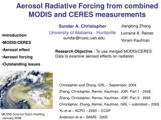
The MODIS Aerosol Retrieval Algorithms Developed by Yoram Kaufman, Didier Tanre, Shana Mattoo Lorraine Remer, Rob Levy, Allen Chu, Vanderlei Martins and many others
Environmental Radiation budget Cloud formation and rainfall Visibility Human Health Respiratory ailments Heart disease The Importance of Aerosols (a brief list)
Total Amount Size distribution Geographic location and transport Spatial distribution in the horizontal and vertical Shape Optical properties Chemical properties What do we want to know about aerosols to determine their impacts?
Total Amount Size distribution - over ocean Geographic location and transport Spatial distribution in the horizontal Optical properties - light scattering MODIS on its own can significantly help us to determine: • MODIS on its own tells us little or nothing about: • Size distribution - over land • Spatial distribution in the vertical • Shape • Optical properties - absorption • Chemical properties
MODIS makes no direct measurements of the physical properties of aerosols. MODIS measures only reflected radiation and this signal is used to derive the physical properties of the aerosols!
Ocean and Land algorithms are totally separate but use similar techniques to derive aerosol properties. To increase the signal to noise ratio in the data we use a statistical approach that groups many pixels. Both algorithms are applied to individual boxes of 20 x 20 pixels at 500 Meter resolution Both algorithms produce 10 Km products. Two MODIS Algorithms
If all pixels in the 10 x 10 kilometer box are ocean the Ocean Algorithm is used. If any land pixels are observed in the 10 Km box the Land Algorithm is used. The MOD35 cloud mask product is used to determine if each pixel is land or ocean. Land or Ocean
ATT & EPH • spacecraft attitude • spacecraft position • Level 0 • raw digital counts • native binary format • GEO MOD03 • geolocation • radiant path geometry • Level 1A • raw digital counts • HDF formatted • MOD02 • Level 1B • calibrated • radiances • converted • telemetry MODIS retrieval algorithms make use of a carefully calibrated and properly geo-located signal.
We can think of any remote sensing retrieval algorithm as having three phases: Removing distortion from the signal Separating signal from noise Correctly interpreting the signal
GAS Correction Most earth science remote sensors have to take into account changes in the signal due to atmospheric gases - water vapor, ozone and CO2. Removing Distortion
To correct the top of atmosphere (TOA) reflectance signal for the effects of atmospheric gasses MODIS uses: Ancillary (outside) Data NCEP, GDAS - meteorological data for water vapor TOVS or TOAST - ozone analysis. If these are not available climatological data is used as a first guess assumption for these values. Removing DistortionGas Correction
Separating signal from noise: Cloud Masking Sediment Masking Statistical treatment of pixels Glint Masking Ocean Algorithm
Spatial Variability Tests Visible channel brightness Cirrus Cloud Removal -- Near IR Tests MOD35 Cloud Product Tests -- Infrared Tests Cloud Masking
Areas of aerosol are usually quite uniform and look “smooth” to our eyes. Clouds are generally much less uniform and look “bumpy”. 3 x 3 boxes of pixels within the 10 Km Box are evaluated in the 0.55μm channel to see if they are uniform or variable. Spatial Variability
Any group of 9 pixels with : Standard deviation > 0.0025 is identified as cloud The upper left pixel of this group is discarded. Information is used from neighboring pixels to the right and below the 10 Km box to evaluate the status of pixels near the edge. The 10 Km boxes at the right hand edge of the swath and at the end of the granule are discarded. Spatial Variability
Cloud Cloud Dust Plume Dust Aerosol Cloud Cirrus Cloud Cloud Shadow
Dust plume incorrectly masked due to high variability Cirrus clouds not detected Results of 3 x 3 Variability cloud screening Dust Plume Center of large “smooth” clouds not detected
Dust Plume restored by “sanity” check This is a spectral test using the ratio of 0.47 / 0.66 < 0.75 We see this naturally since the absorption in the blue makes dust look brown to our eyes
Areas of large “smooth” clouds left by the spatial variability tests are identified by their brightness in the visible range using the threshold 0.47 > 0.4
In some cases the cirrus tests will not return a firm conclusion that the pixel is a cirrus cloud. Cirrus clouds are identified by a combination of infrared and near-infrared tests. There are 3 tests we apply to identify Cirrus clouds If any one of these tests indicate cirrus is present we label the pixels as cloudy and mask them In this case we label the pixel as “non-cloudy” but reduce the quality of the retrieval for the whole 10 x 10 Km box
After screening for clouds we look for and eliminate: • Sediments • Glint to within 40 degrees of the specular refelection • If there are • at least 10 remaining pixels in • the 0.86m channel • and 30 remaining pixels in • all of the other channels • we will attempt to make an aerosol retrieval We further eliminate the brightest 25% and darkest 25% of the remaining pixels in the 0.86 channel. This is done to eliminate any remaining outliers so that we can arrive at the “true” mean reflectance values for the box. If the pixels that are eliminated in this final step include those that reduce the quality of the retrieval, the high quality flag is restored.
We will not attempt to make an ocean aerosol retrieval in any 10 km box where: Any pixel is identified as land It is cloudy There is glint Reflectance in the 0.86μm is too low to retrieve AOD. Total number of available wavelengths < 3 Insufficient number of visible/SWIR bands (between 0.55μm and 1.24μm) Angles are out of bounds AOD (0.55μm) > 5 AOD (0.55μm) < -0.01 Retrieval Conditions
We need to make several assumptions to correctly infer the aerosol characteristics from the remaining signal. Assumptions include: Surface reflectance values A bi-modal aerosol distribution A set of aerosol properties (models) for each of the aerosol modes. Assumptions
The spectral reflectances measured by the satellite from the remaining pixels contain elements of both the ocean surface and atmospheric aerosols. We still need to remove surface effects. Separation of signal and noise
Contributions to the total signal due to the ocean surface include: Sun glint reflection from surface waves Reflection from whitecaps Lambertian reflectance from underwater scattering. Ocean Surface
After removing as much of the noise as possible due to the surface signal we are left with an optical signal representing aerosols that must be correctly interpreted. We are still very limited in our ability to correctly infer the aerosol properties from this signal. We use our knowledge and experience to construct models of aerosols which represent real world conditions. With the help of these models we can correctly Interpret the measured signal.
Aerosol “models” over oceanAre represented by theoretical “modes” ATBD
reflectance wavelength 0.10 0.20 1.0 2.0 MODIS aerosol retrieval over ocean Find one coarse mode and one fine mode that combine to match the observed spectral reflectances Radius (µm)
Look Up Tables - LUT The radiative transfer code is computationally time consuming. To make the radiative transfer code run more efficiently we make use of a set of pre-computed tables for the various sets of possible angles and amounts of aerosol. We interpolate from the values in the table for angles and aot values not in the LUT
Creating the LUT We must consider which atmospheric scenarios (combination of aerosol + Rayleigh + surface + other) are representative of what MODIS observes (including appropriate geometry, MODIS bandwidth information, etc). LUT utilizes vector radiative transfer (vRT) code to simulate: • a,T,s: (path radiance, transmission, backscattering) • Combination of Rayleigh + Aerosol • s (surface reflectance) • Combination of foam / whitecaps (assuming V=6 m/s) + water leaving radiance” (nonzero at 0.55 m only)