Download
1 / 59
600 likes | 829 Views
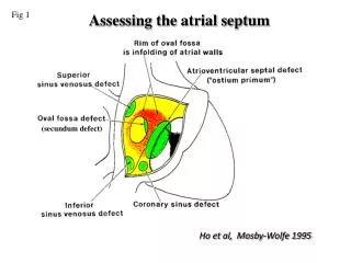
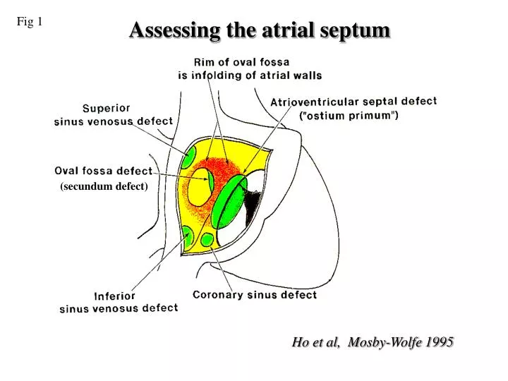
Fig 1. Assessing the atrial septum. (secundum defect). Ho et al, Mosby-Wolfe 1995. Fig 2. Secundum ASD. RA. LA. Apical four chamber view demonstrating a dilated right heart and possible secundum atrial septal defect (arrow point). Subcostal four chamber view of same patient

E N D
Fig 1 Assessing the atrial septum (secundum defect) Ho et al, Mosby-Wolfe 1995
Fig 2 Secundum ASD RA LA Apical four chamber view demonstrating a dilated right heart and possible secundum atrial septal defect (arrow point) Subcostal four chamber view of same patient confirming a left to right shunt at atrial level
Fig 3 Secundum ASD Apical four chamber view demonstrating a large secundum atrial septal defect
Fig 4 TOE secundum ASD LA RA Transesophageal longitudinal view of the atria demonstrating an ostium secundum defect. Colour flow image from the same view demonstrating left-to-right shunting across the ASD
Fig 5 Primum ASD LV RV RA LA Apical four chamber view demonstrating a primum atrial septal defect Colour Doppler flow image from same view illustrating left-to-right shunt across the primum atrial septal defect
Fig 6 Parasternal short axis view demonstrating tri-leaflet left atrioventricular valve in a patient with a primum atrium septal defect
Fig 7 Primum ASD Subcostal four chamber view demonstrate an large primum atrial septal defect which is located at the low part of normal atrial septum and the junction with atrioventricular valve. LA RA LV RV
Fig 8 SVC type ASD • Apical four chamber view showing a sinus venous defect of the superior vena caval type
Fig 9 SVC type ASD (TOE) LA RA SVC Colour flow image from the same view demonstrating left-to-right shunting across the ASD Transesophageal longitudinal view of the atria demonstrating a sinus venousus defect of the superior vena caval type.
Fig 10 Sinus venousis ASD (SVC type) Transesophageal longitudinal view of the atria demonstrating a sinus venosus defect of the superior vena caval type.
Fig 11 Ventricular septal defects PA Doubly committed subarterial defect Muscular defect RA Perimembranous defect RV Diagram of the ventricular septum seen from right ventricular aspect, showing the positions of various types of ventricular septal defects.
Fig 12 Small perimembranous VSD • Echocardiogram demonstrating shunting through a perimembranous ventricular septal defect. Parasternal long-axis view with the transducer tilted toward the right ventricular inflow. RV LV LA
Fig 13 Large perimembranous VSD with PH LV MPA RV AO LA RA Parasternal short axis view from same patient showing significantly dilated main pulmonary artery, indicating the presence of pulmonary hypertension Apical four chamber view demonstrating a large perimembranous inlet ventricular septal defect
Fig 14 Muscular VSD Apical five chamber view demonstrating a small muscular outlet ventricular septal defect (arrow) LV RV AO
Fig 15 Doubly committed VSD RV PA vsd Ao RA LA LA Modified Parasternal short axis view demonstrating the presence of doubly committed subarterial ventricular defect (arrow). Note there is no septal tissue between aortic and pulmonary valve.
Fig 16 Complete atrioventricular septal defect Apical four chamber view from a patient with complete AV septal defect. Note the large atrial and ventricular septal defects with a common atrioventricular valve.
Atrioventricular septal defect Fig 17 LA RA LV LV RV RV Apical four chamber view showing a complete atrioventricular septal defect Subcostal coronal position with slight obliquity. Image taken during diastole; the common atrioventricular valve in the open position.
Fig 18 Patent Ductus Arteriosus PDA Ao PA
Fig 19 b b PDA RVOT PDA a Ao MPA Ao c c PDA D Ao a: Parasternal short axis view, showing the position of a patent ductus. b:Colour flow mapping showing a left to right shunt through the duct. C:Continuous wave Doppler recording from the duct flow showing continuous flow with a peak velocity of 4.2 m/s.
Fig 20 Pulmonary valve stenosis RVOT MPA Continuous wave Doppler trace demonstrating very high systolic velocity and the small ‘a’ wave during atrial systole. The later is the sign for restrictive right ventricular physiology. Parasternal short axis view of a thickened and stenotic pulmonary valve (arrow). Note that poststenotic dilatation of main pulmonary artery, and significant right ventricular hypertrophy
Fig 21 Pulmonary Regurgitation A B Continuous wave Doppler recording obtained from the parasternal position directed through pulmonary valve. A: From a patient with mild PR, note the regurgitation signal persist till the end of diastole. B: Patient with severe pulmonary regurgitation; the regurgitation signal ends at the middle of diastole.
Fig 22 Bicuspid AV Parasternal long axis view demonstrating eccentric valve closure in a patient with a bicuspid aortic valve; note the aortic root is dilated as well. Parasternal short axis view of aortic root; a bicuspid aortic valve can be identified within the aortic root.
Fig 23 Bicuspid aortic valve causing aortic stenosis Parasternal long axis view in a patient with a bicuspid aortic valve, demonstrating thickened valve leaflets. Doppler colour flow demonstrating the proximal acceleration and distal flow disturbance.
Fig 24 Bicuspid aortic valve with AR RV Ao LV Ao LV LA LA Parasternal long axis view in a patient with a bicuspid aortic valve, demonstrating thin but doming aortic valve leaflets. Doppler colour flow demonstrating the aortic valve regurgitation during diastole.
Fig 25 Congenital AS RV Ao Ao LV Parasternal longaxis and short axis view showing a congenital aortic stenosis causing by a possible unileaflet aortic valve. The valve leaflet itself looks dysplastic.
Fig 26 Sub AS b a LV RV LV vsd RV Ao LA c a:Apical five chamber view demonstrating a sub-aortic ridge. b:Colour flow Doppler showing turbulent flow start from sub-aortic area and a shunt through a VSD. c: Continuous Doppler trace from the LVOT showing a peak velocity of 4.2 m/s
Fig 27 Sub aortic stenosis Ao LV Parasternal long axix view demonstrating a sub-aortic fibrio-muscular ridge (arrow).
Fig 28 Small Aortic Root Colour Doppler demonstrate mild aortic regurgitation Parasternal long-axis view of a fibromuscular subaortic tunnel. The aortic root itself is also small
Fig 29 COA Suprasternal long-axis view of the aorta. There is shelf at the site of the ductal junction causing narrowing Colour Doppler flow map through the descending aorta shows aliasing at the site of narrowing.
Fig 30 Spectral Doppler recording through the descending aorta demonstrating high velocity during systole, and continued flow during diastole. Continuous flow detected in abdominal aorta.
Fig 31 Congenital mitral valve stenosis Ao LV LA Parasternal long axis view showing congenital mitral stenosis. Note the thickened valve leaflets with a small opening orifice. The left atrium is dilated due to the mitral stenosis.
Fig 32 A B LV LA C A. Parasternal short axis view demonstrating a parachute type abnormality of the mitral valve. Note the small valve orifice (arrow) due to all chordae attached to the single anteriolateral paplliary muscle. B. Colour flow mapping showing flow acceleration through the valve during diastole. C. Continuous wave Doppler trace showing increased flow velocity
Fig 33 MVL prolapse Ao LV LA Colour Doppler flow mapping showing anteriorly directed mitral regurgitation jet. Parasternal long-axis view demonstrating mitral valve prolapse.
Fig 34 Mitral Valve Prolapsing LA RA LA LV RV Transesophageal echocardiogram showing posterior leaflet mitral valve prolapse. Colour Doppler mapping demonstrating severe mitral regurgitation in the same patient.
Fig 35 Ebstein’s anomaly RA RA Apical four chamber view in Ebstein’s malformation of tricuspid valve showing the degree of displacement of the septal leaflet Colour Doppler flow map demonstrating tricuspid regurgitation in the same patient.
Fig 36 Tetralogy of Fallot
Fig 37 Tetralogy of Fallot RVOT RV VSD Ao LV Ao Parasternal long axis view showing aortic overriding and large sub-aortic VSD (arrow) in a patient with Tetrology of Fallot. Parasternal short axis view demonstrating The right ventricular outflow tract is narrowed by the outlet septum.
Fig 38 Tetralogy of Fallot RVOT Ao Continuous wave Doppler trace taken from the RVOT showing the peak velocity of more than 4 m/s. Colour Doppler showing a narrowed right ventricular outflow tract (RVOT) with turbulent flow.
Fig 39 Transposition of Great Arteries Parasternal long axis view from a patient with transposition of the great arteries. Note the two great arteries are parallel and the pulmonary artery is positioned posterior to the aorta.
Fig 40 Congenitally Corrected Transposition of Great Arteries (CC-TGA) Apical four chamber view of patient with congenitally corrected transposition of the great arteries. Note the presence of a moderator band (arrow) and the apical displacement of the left sided atrioventricular valve, distinguishing the left sided ventricle is a morphological right ventricle. MRV MLV LA RA
Fig 41 Congenitally Corrected Transposition of Great Arteries (CC-TGA) MRV MRV MLV MLV PA LA RA Apical five chamber view showing a pulmonary artery which bifurcates and arises from right sided morphological left ventricle Apical four chamber view showing a left sided morphological right ventricle with moderater band and an apically displaced tricuspid valve.
Fig 42 Double outlet of right ventricle (DORV) RV Ao LV LA Parasternal long axis view of a patient with a double outlet right ventricle and a sub-aortic VSD, demonstrating the aorta is mainly arising from RV, and the separation between the mitral valve apparatus and the base of the aortic root (arrow)
Fig 43 Double Outlet Right Ventricle LV vsd RV PA Ao Apical five chamber view in patient with double-out right ventricle. Note both aorta and pulmonary artery are arising from right ventricle with the aorta more anterior and on the right side of the pulmonary artery.
Fig 44 Double inlet Left Ventricle LV Apical four chamber view showing double inlet left ventricle. Note the presence of two atrioventricular valves connecting to a single morphology left ventricle. MLV RV RA LA LA LA RA
Fig 45 Tricuspid atresia LV RV vsd LA RA Apical four chamber view from a patient with an absent right atrioventricular connection (tricuspid atresia). The position of the tricuspid valve is replaced by strand of tissue (arrow). The right ventricular cavity is very small. A perimembranous VSD is also present.
Fig 46 Residual VSD Parasternal long-axis view showing a residual VSD. The echogenic patch on the septum suggests a previous repair. RV LV AO LA
Fig 47 Primum ASD repaired LV LA Apical four chamber view of patient with a primum ASD repair. Note the thickened left AV valve leaflet and markedly dilated left atrium Colour Doppler flow mapping of the same patient demonstrating severe left AV valve regurgitation.
Fig 48 Re-coarctation Continuous wave Doppler trace across the coarctation area showing a long diastolic tail. Supra-sternal view of the aortic arch in a patient with previous repaired coarctation of the aorta. Note the narrowing at the previous repaired area. The bright echo from the aortic wall suggests previous surgery.
Fig 49 Repaired Fallot LV RV RVOT LA Ao RA RA Parasternal short axis view showing a residual right ventricular outflow tract obstruction in an adult patient with repaired Tetralogy of Fallot Apical four chamber view demonstrating a severely dilated RA from long standing high right ventricular pressure and tricuspid regurgitation.
Fig 50 RV LV Apical four chamber view in a patient with transposition of the great arteries after a Mustard repair. Note the intra-atrial baffle (arrow) directing the pulmonary venous flow into the right side atrium. The right atrium and right ventricle are dilated. Mustard Procedure