Download
1 / 38
410 likes | 716 Views
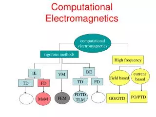
Electromagnetics (ENGR 367). Types of T-lines and Their Applications. Outline of Lecture. Identify Types of T-lines versus Waveguides Detail construction and applications of each type Provide formulas for T-line parameters of each type that depend on LF or HF operation

E N D
Electromagnetics(ENGR 367) Types of T-lines and Their Applications
Outline of Lecture • Identify Types of T-lines versus Waveguides • Detail construction and applications of each type • Provide formulas for T-line parameters of each type that depend on • LF or HF operation • Lossy or Lossless conditions • Show examples of T-line parameter calculation • Draw some conclusions
Types of T-lines • Coaxial cable • Two-wire line • Stripline and Microstrip Line • Other specialized variations
T-lines versus Waveguides • T-lines operate in the TEM mode only (Transverse ElectroMagnetic waves) • Waveguides carry EM waves that • May propagate in the TM or TE modes at higher frequencies and may perform more efficiently than T-lines in the microwave range • Take a zig-zag path as they reflect off the conducting boundaries and propagate along the main axis of the waveguide
Detailed Description of IndividualT-line Types and Their Applications • Coaxial Cable: Basic Construction Radio-grade flexible RG-59 (Z0 = 75 ) coaxial cable. A: outer plastic sheathB: copper screenC: inner dielectric insulatorD: copper core Other standard types have similar construction. from http://en.wikipedia.org/wiki/Coax
Coaxial Cable • Other aspects of basic construction • Stiffness options available on the market • Flexible type: has braided sheath • Rigid type: has a solid sheath (Sheath in either case typically made of Cu) • Dielectric insulating layer • Thickness and permittivity determine • Characteristic Impedance (Z0) • Attenuation () • May be either solid or perforated
Applications of Coaxial Cable • Short runs to connect • Home video equipment • Ham radio setups (transciever antenna) • Satellite TV (dish Rx set) • Cable modem & VSAT for Internet Access • Broadcast radio communication (Tx ant.)
Applications of Coaxial Cable • Long runs to connect • Formerly radio and TV networks (Now replaced by optical and satellite networks) • Presently cable TV signals
Specialized Variations of Coax • Triaxial Cable (triax): includes a 3rd layer of shielding, insulation and sheathing, the latter is grounded to further reduce outside interference • Twin-axial cable (twinax): balanced twisted pair within a cylindrical shield for shielded and balanced differential signals • Multi-conductor coax
Review Skin Depth • A measure of the depth electromagnetic waves penetrate into a conductor where the amplitude has decayed by e-1 = 0.368 • Note that as frequency (f) increases, the skin depth becomes smaller and more significant!
T-line Parameters for Coax(from Hayt & Buck, 7/e, pp. 483-484) • Assuming HF operation such that the skin depth << a = radius of inner conductor • Lossless approx. (R << wL and G << wC): • Modifications for the lossy case:
T-line Parameters for Coax(from Hayt & Buck, 7/e, p. 485) • Modifications for LF operation where the skin effect is negligible ( >> a): current distributes uniformly throughout conductor cross-sections • Resistance of conductors increases
T-line Parameters for Coax(from Hayt & Buck, 7/e, p. 485) • Modifications for LF operation ( >> a): • Internal inductance of conductors becomes significant • For intermediate frequencies ( a): • Expressions for parameters become more complicated • One can refer to handbook values as needed
Example of Parameter Calculations for Coax • Exercise 1 (D14.2a, H&B, 7/e, p. 486) Given: a coax T-line with a = 4 mm, b = 17.5 mm, and c = 20 mm. Each conductor has = 2 x 10⁷ S/m, and the dielectric has r = 1, r = 3, and / = 0.025. Find: L, C, R, G, and Z0 at 150 MHz. Solution: 1st find the skin depth; compare to a
Example of Parameter Calculations for Coax • Exercise 1 (continued) • Solution: next calculate coax T-line parameters
Example of Parameter Calculations for Coax • Exercise 1 (continued) • Solution: check validity of lossless approx. for Z0
Two-wire Line • Basic Construction • Two parallel circular conductors of equal radius and conductivity enclosed in a plastic insulating material • Dielectric insulator • Provides mechanical spacing and some rigidity • Affects Z0 and
Applications of Two-wire Line • As a lead-in to carry low level signals from antenna over a short run to a TV or FM Rx • Connections in regular telephone networks • In the conceptual development of a more sophisticated waveguide systems (Fast Neutron Research Facility of CMU www.fnrf.science.cmu.ac.th/theory/ waveguide/Waveguide%20theory%202.html)
Parameters of Two-wire Line(from Hayt & Buck, 7/e, pp. 486-487) • For HF operation ( << a): • Lossless approximation
Parameters of Two-wire Line(from Hayt & Buck, 7/e, pp. 486-487) • For HF operation ( << a): • Modifications for Lossy conditions • In LF operation: must modify above by including R and L over entire cross-section of conductors as for coax
Parameters of Two-wire Line(from Hayt & Buck, 7/e, p. 487) • For LF operation ( >> a): • Inductance per unit length increases by twice the internal inductance of a straight round wire • Resistance per unit length becomes twice the dc resistance of a wire of radius a and conductivity c
Example of Parameter Calculation for Two-wire Line • Exercise 2 (D14.3, H&B, 7/e, p. 487) Given: a two-wire T-line with conductors each of radius 0.8 mm and conductivity 3 x 10⁷ S/m, separated by 0.8 cm in a dielectric where r = 2.5, r = 1, and d = 4x10⁻⁹ S/m Find: , C, G, L & R at 60 Hz Solution: validate LF model by comparing to a
Example of Parameter Calculation for Two-wire Line • Exercise 2 (D14.3, H&B, 7/e, p. 487) Solution: calculate the LF two-wire T-line circuit param’s
Striplines and Microstrip Lines • Basic Construction: Stripline • Single or double track strip of Cu imbedded in dielectric material sandwiched between conducting ground planes on top and bottom
Striplines and Microstrip Lines • Basic Construction: Microstrip • Single or double track strip of Cu on top of a dielectric substrate material above a single conducting ground plane • In practice, superstrate material may be other than air
Striplines and Microstrip Lines • Basic Construction: dielectric material For HF applications, special substrate and superstrate (if present) materials must be used with high uniformity and low loss tangent (tan = ’/’) such as Rogers RT Duroid or FR4 as manufactured for this application (common PCB will not work!)
Applications of Stripline & Microstrip Line • Trace connections between devices in PCB microelectronic circuits • T-line connections between HF devices easily integrated with surface mount, distributed elements and microstrip antennas. • HF communication systems and devices with compact, flat, lightweight, constraints and short run requirements such as cell phones, portable PCs and and other wireless mobile devices
Parameters for Microstrip Line (Single Track) • If the strip width is large (w >> d), then the structure acts like a parallel plate line where for the low loss case
Parameters for Microstrip Line (Single Track) • If w d or w < d (as typical for microstrip) then a quasi TEM mode may be assumed to account for the propagation of waves through the two different materials (e.g., air or superstrate and substrate dielectrics) • At low frequencies (f < 1.5 GHz) assuming negligible losses over a short run the propagation velocity is
Parameters for Microstrip Line (Single Track) • Definition of Effective Dielectric Constant (r,eff): acts as a weighted average of the air (or superstrate) and substrate dielectric constants with a proportion determined by the field filling factor (q)
Parameters for Microstrip Line (Single Track) • Empirical Formulas for r,eff assuming w/d > 1.3 • in terms of w/d for application to the dimensions of a pre-fabricated line • In terms of r and Z0 for finding the necessary r,eff based on a desired Z0
Parameters for Microstrip Line (Single Track) • Characteristic Impedance (Z0): • Based on the air-filled equivalent microstrip line • For w/d < 3.3
Example of Parameter Calculation for Microstrip Line • Exercise 3 (D14.4, H&B, 7/e, p. ) Given: a 2 mm wide microstrip line is fabricated on a 1 mm thick substrate of lithium niobate (r = 4.8). Find: r,eff, Z0 and vp Solution: since w/d = 2 > 1.3:
Conclusions • Types of T-lines such as coax, two-wire, microstrip lines and other variations have • relative advantages in certain applications • a unique construction that determines their circuit parameters • Circuit parameters of T-lines depend on LF or HF operation as indicated by skin depth versus conductor size; parameters may be found by calculation or in a handbook
Conclusions • While coax has shielding to minimize interference in low signal applications, it may be too large and bulky for PCB and microelectronic circuit applications • While microstrip lines are easy to fabricate and compatible with microelectronic systems, they are analytically complex requiring numerical methods for accuracy
Conclusions • For higher frequency applications, waveguides (including rectangular or cylindrical “pipes,” parallel plates, dielectric slabs and optical fiber types) become more efficient than T-lines • The analysis of waveguides becomes a more advanced task with fully EM field wave equations
References and Other Resources • Hayt & Buck, Engineering Electromagnetics, 7/e, McGraw Hill: New York, 2006. • Kraus & Fleisch, Electromagnetics with Applications, 5/e, McGraw Hill: New York, 1999.