Download
1 / 3
30 likes | 180 Views
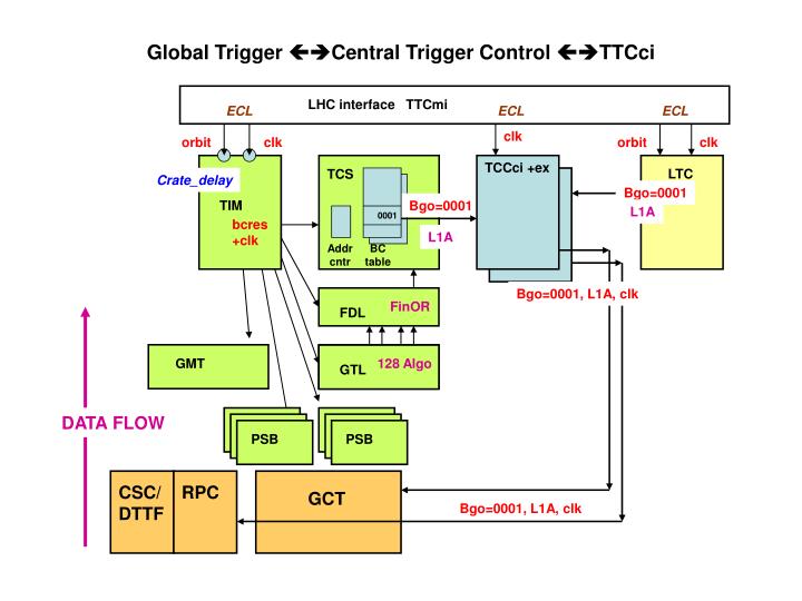
Global Trigger Central Trigger Control TTCci. LHC interface TTCmi. ECL. ECL. ECL. clk. orbit. clk. orbit. clk. TCCci +ex. LTC. TCS. Crate_delay. Bgo=0001. TIM. Bgo=0001. L1A. 0001. bcres +clk. L1A. Addr cntr. BC table. Bgo=0001, L1A, clk. FinOR. FDL. 128 Algo.

E N D
Global Trigger Central Trigger Control TTCci LHC interface TTCmi ECL ECL ECL clk orbit clk orbit clk TCCci +ex LTC TCS Crate_delay Bgo=0001 TIM Bgo=0001 L1A 0001 bcres +clk L1A Addr cntr BC table Bgo=0001, L1A, clk FinOR FDL 128 Algo GMT 128 Algo GTL GTL DATA FLOW PSB PSB CSC/ DTTF RPC GCT Bgo=0001, L1A, clk
Structure: • TTCmi(LHC) sends CLOCK(ecl) to TIM(GT), TTCci and LTC. • TTCmi(LHC) sends ORBIT (ecl) to GT-TIM and LTC • TIM(GT) sends ‚clk‘ + bcres‘ to all GT and GMT boards and to TCS. • TCS sends L1A and Bgo=0001(as ‚bcres) to all 32 TTCci. • 32 TTCci send clk, L1A, Bgo=0001(as ‚bcres) to all detector partitions. • Synchronisation to LHC in 3 steps: • 1.) Crate_delay in TIM(GT) • Adjust it so that data from BC=0 go into address=0 of spy_memory • and Ringbuffer on the GMT and PSB boards • 2.) For each DAQ_partition load Bgo=0001 into a BC_table address so that it arrives well before needed by connected subdetectors. • 3.) Delay Bgo=0001 so that it arrives at the correct time in the subdetector.
CAEN VME CONTROLLER 1 PC: RUN Control 2 FREE VME 3 FREE VME 4 L1A L1A_OUT 5 Detector subsystems 6 L1A_OUT aTTS DAQ APV-EMULATORS 7 TCS STATUS SIGNALS 8 TECHNICAL TRIGGER SIGNALS PSB 9 LEVEL 1 GLOBAL TRIGGER 9U-VME CRATE 128 Algo FDL 10 GTL 11 12 spare Backplane PSB 4IEG, 4EG, 4JET, 4fJET 13 4TAU-JET, ET*, JetNr, 14 PSB (ET*=total ET, HT, MET) PSB 15 TOTEM 16 CLK, ORBIT TIM TTC - GPS-TIME S-links: DAQ, EVM 17 GTFE GMT 18 8 RPC muons 4 DT muons 4 CSC muons 19 PSB 20 PSB 21 PSB MIP/QUIET bits