Download
1 / 246
2.48k likes | 2.79k Views
Editing the standard MOCMOS technology of GNU Electric version 8.08. by Kazzz (a Japanese engineer) Revision: 0.5 Date: June 07 th , 2009. Revision history. ※ Mostly spending after the office hours …. Objectives.

E N D
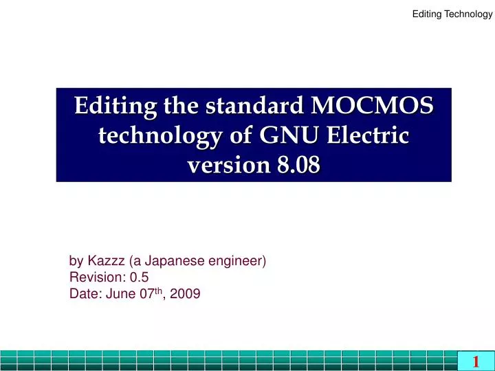
Editing the standard MOCMOStechnology of GNU Electricversion 8.08 by Kazzz (a Japanese engineer) Revision: 0.5 Date: June 07th, 2009
Revision history ※ Mostly spending after the office hours …
Objectives • To enhance the standard MOCMOS technology so that it has two resistor types below for analog circuit design • N-well resistor • Poly-2 high-resistor • To make the entire technology including the newly added resistors • NCC tool applicable • DRC tool applicable • To make the newly added resistor types SPICE-parameter- extraction applicable
Acknowledgments • Thanks to Dr. Steven M. Rubin and all the developers of this VLSI design suite for providing such a fascinating tool under GNU General Public License. • Availability of this tool has made me decide to re-study integrated circuit design, especially CMOS, after about 2-decade gap. • More than 20 years ago, having this kind of tool on a personal computer was beyond dream, especially for those who were using the first generation of GE Calma® on a mini-computer having only 64-KByte of main memory!
Warnings • Throughout this document, the physical parameters such as sheet resistance, parasitic capacitance per unit length, design rules, etc. are all artificial and do not aspire to any accuracy. • As stated in the previous slide, the main aim of this document is to capture and clarify different steps that may be required to introduce a new technology to GNU Electric. • For more realistic design and simulation, we MUST consult our foundry or in-house process engineers about those parameters and need fine tunings.
References Please refer to : [1] last updated June 2nd, 2009 [2] http://java.com/en/ for Java [3] http://www.eclipse.org/for Eclipse [4] http://www.staticfreesoft.com/productsFree.html for GNU Electric ✔
Java Runtime and SDK The images were captured on Japanese Windows throughout this document. Therefore, wherever you see a Yen mark in a file path, please understand that it corresponds to a “back slash” character in the non-Japanese world. • The tools listed below are assumed as Java runtime and development environment
Some icons used throughout this presentation 8.2 Section of the manual to be referred to • Duplicate the N-well # 01 # 02 # 03 Micro-steps to be followed sequentially
The final course materials Here is the latest and final course materials as of June 07th, 2009. You will find some intermediate materials embedded in this document, which were created while studying about this theme. Return to this slide after reaching the end of this document; far more than 240 slides.
Index Part-I Editing the Technology Skeleton Part-II Testing the Technology Skeleton Part-III Tuning the Technology for LT-Spice Simulation Part-IV Editing the Design Rules Part-V Testing the Design Rules
Part-I Editing the Technology Skeleton
01. Convert the existing technology for editing 8.2 # 01 • Assume use of 3 metal layers
OK Cancel ※ Images are captured on Japanese Windows XP # 02 # 03
# 04 # 05 • Let the new technology name be “mocmos-plus.” # 06
02. Editing layer cells for N-well resistor 8.4 The manual says …
The cross-sectional view of an N-Well resistor under its contact node will be … • Physically the same as but logically different from N-Select layer • Physically the same as but logically different from N-Well layer
8.4 • Duplicate the N-well to derive “N-Well-Resistor” # 01 # 02 # 03
# 04 • Don’t change GDS-II layer as this has the same physical layer as “N-Well”
Let the boarder be “solid-thick” style # 05 # 06
Duplicate the N-select for better Ohmic contact # 07 # 08 # 09
# 10 • Don’t change GDS-II layer as this has the same physical layer as “N-Select”
Change the layer function and boarder style # 11 # 12 # 13
03. Editing a layer cell for Polysilicon-2 resistor • Polysilicon-2 resistor will be made as below • Polysilicon-2-HighResistor prevents Polysilicon-2-Resistor from being highly doped, hence, high sheet resistance. Top view • Physically the same as but logically different from Polysilicon-2 layer • Regions uncovered by Polysilicon-2-HighReistor will be highly doped, hence, low ohmic contact resistance
The cross-sectional view of a Polysilicon-2 resistor under its contact node will be … • Physically the same as but logically different from Polysilicon-2 layer
8.4 • Duplicate the polysilicon-2 # 01 # 02 # 03
# 04 • Don’t change GDS-II layer as this has the same physical layer as “Polysilicon-2” Just a guess
Change the boarder style and color # 05 # 06
# 07 # 08 • Confirm that these 3 layers have been added
04. Editing a layer cell for Polysilicon-2 high-resistor 8.4 • Duplicate the polysilicon-2 # 01 # 02 # 03
# 04 Just a place filler Above Poly2 by 1.0
# 05 • Confirm that these 4 layers have been added
05. Editing an arc cell for N-well resistor 8.5 • Duplicate the N-well # 01 # 02 # 03
Change the layer to “N-Well-Resistor” # 05 # 06 • Notice that the boarder style has been changed
Change the min. y size of both the boxes to “5” # 07 # 08 • Then optionally move them down so that the top y-coordinate be zero (at the origin)
06. Editing an arc cell for Polysilicon-2 resistor 8.5 • Duplicate the Polysilicon-2 # 01 # 02 # 03
# 05 # 06 • Notice that the boarder style and color have been changed
# 08 • Confirm that these 2 arcs have been added
07. Editing an arc cell for Polysilicon-2 high-resistor 8.5 • Duplicate the Polysilicon-2 # 01 # 02 # 03
# 05 # 06 • Notice that the boarder style and color have been changed
# 08 • Confirm that these 3 arcs have been added
08. Editing a pin node for N-well resistor 8.6 • Duplicate the N-well pin # 01 # 02 # 03
Change the layer of each of the four boxes to “N-Well-Resistor” # 05
Confirm the layer used # 06 # 07