Download
1 / 38
380 likes | 730 Views
Electric Forces and Fields. Chapter 16. Electrical Field. Maxwell developed an approach to discussing fields An electric field is said to exist in the region of space around a charged object

E N D
Electric Forces and Fields Chapter 16
Electrical Field • Maxwell developed an approach to discussing fields • An electric field is said to exist in the region of space around a charged object • When another charged object enters this electric field, the field exerts a force on the second charged object
Direction of Electric Field • The electric field produced by a negative charge is directed toward the charge • A positive test charge would be attracted to the negative source charge
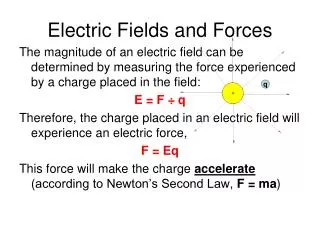
Electric Field, cont. • A charged particle, with charge Q, produces an electric field in the region of space around it • A small test charge, qo, placed in the field, will experience a force See example 15.4 & 5
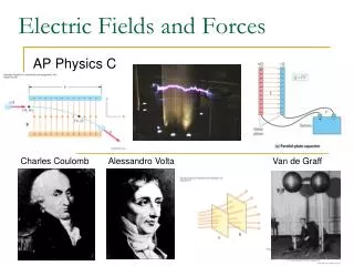
Coulomb’s Law • Mathematically, • ke is called the Coulomb Constant • ke = 8.99 x 10⁹ N m2/C2 • Typical charges can be in the µC range • Remember, Coulombs must be used in the equation • Remember that force is a vector quantity
Electric Field Line Patterns • Point charge • The lines radiate equally in all directions • For a positive source charge, the lines will radiate outward
Electric Field Lines, cont. • The field lines are related to the field as follows: • The electric field vector, E, is tangent to the electric field lines at each point • The number of lines per unit area through a surface perpendicular to the lines is proportional to the strength of the electric field in a given region
Electric Field Line Patterns • For a negative source charge, the lines will point inward
Electric Field Line Patterns • An electric dipole consists of two equal and opposite charges • The high density of lines between the charges indicates the strong electric field in this region
Electric Field Line Patterns • Two equal but like point charges • At a great distance from the charges, the field would be approximately that of a single charge of 2q • The bulging out of the field lines between the charges indicates the repulsion between the charges • The low field lines between the charges indicates a weak field in this region
Electric Field Patterns • Unequal and unlike charges • Note that two lines leave the +2q charge for each line that terminates on -q
Electric Field • Mathematical Definition, • The electric field is a vector quantity • The direction of the field is defined to be the direction of the electric force that would be exerted on a small positive test charge placed at that point
Chapter 17 Electric Energy and Current
Work and Potential Energy • For a uniform field between the two plates • As the charge moves from A to B, work is done in it • W = F d= q E d • ΔPE = - W = - q E d • only for a uniform field
Summary of Positive Charge Movements and Energy • When a positive charge is placed in an electric field • It moves in the direction of the field • It moves from a point of higher potential to a point of lower potential • Its electrical potential energy decreases • Its kinetic energy increases
Summary of Negative Charge Movements and Energy • When a negative charge is placed in an electric field • It moves opposite to the direction of the field • It moves from a point of lower potential to a point of higher potential • Its electrical potential energy decreases • Its kinetic energy increases
Potential Difference • ΔPE = - W = - q E d The potential difference between points A and B is defined as: ΔV = VB – VA = ΔPE / q =-Ed • Potential difference is not the same as potential energy • 1V is defined as 1 J/C 1 Joule of work must be done to move a 1C across 1V potential difference
Electric Potential of a Point Charge • The point of zero electric potential is taken to be at an infinite distance from the charge • The potential created by a point charge q at any distance r from the charge is V is scalar Quantity (superposition applies) • A potential exists at some point in space whether or not there is a test charge at that point • Ex. 16.4 p.540
Potentials and Charged Conductors • W = -ΔPE = -q(VB – VA), • Therefore no work is required to move a charge between two points that are at the same electric potential i.e. W = 0 when VA = VB • For two charges separated by r PE = ke q1q2 r Charged Surfaces and Conductors • All points on the surface of a charged conductor in electrostatic equilibrium are at the same potential
Applications of Capacitors – Camera Flash • The flash attachment on a camera uses a capacitor • A battery is used to charge the capacitor • The energy stored in the capacitor is released when the button is pushed to take a picture • The charge is delivered very quickly, illuminating the subject when more light is needed
Applications of Capacitors -- Computers • Computers use capacitors in many ways • Some keyboards use capacitors at the bases of the keys • When the key is pressed, the capacitor spacing decreases and the capacitance increases • The key is recognized by the change in capacitance
Capacitance • A capacitor is a device used in a variety of electric circuits—Often for energy storage • Units: Farad (F) • 1 F = 1 C / V • A Farad is very large • Often will see µF or pF
Parallel-Plate Capacitor • The capacitance of a device depends on the geometric arrangement of the conductors • For a parallel-plate capacitor whose plates are separated by air: Єo is the permittivity of free space; Єo =8.85 x 10⁻¹² C2/Nm2 A Є = C o d
Energy Stored in a Capacitor • Energy stored = ½ Q ΔV • From the definition of capacitance, this can be rewritten in different forms Q = CV
Electric Current • Whenever electric charges of like signs move, an electric current is said to exist • The current is the rate at which the charge flows through this surface • charges flowing perpendicularly to a surface of area • The SI unit of current is Ampere (A) • 1 A = 1 C/s + + + + +
Electric Current, cont • The direction of current flow is the direction positive charge would flow • This is known as conventional current flow • In a common conductor, such as copper, the current is due to the motion of the negatively charged electrons • It is common to refer to a moving charge as a mobile charge carrier • A charge carrier can be positive or negative • Current I I = ΔQC t S
Meters in a Circuit Remember: 1 V = 1J/C
Resistance, cont • Units of resistance are ohms (Ω) • 1 Ω = 1 V / A • Resistance in a circuit arises due to collisions between the electrons carrying the current with the fixed atoms inside the conductor
Ohm’s Law • Experiments show that for many materials, including most metals, the resistance remains constant over a wide range of applied voltages or currents • This statement has become known as Ohm’s Law • ΔV = I R • Ohm’s Law is an empirical relationship that is valid only for certain materials • Materials that obey Ohm’s Law are said to be ohmic
Ohm’s Law, cont V slope=R I For an ohmic device • The resistance is constant over a wide range of voltages • The relationship between current and voltage is linear • The slope is related to the resistance
Electrical Energy and Power, • The rate at which the energy is lost is the power • From Ohm’s Law, alternate forms of power are • Energy E = Pt W-s or kW-Hr
Capacitors in Parallel(have the same voltage across them) Q1 = C1ΔV Q2 = C2ΔV Q1 + Q2 = Qtot = C1ΔV + C2ΔV = (C1+ C2)ΔV for capacitors in parallel Ceq= C1+ C2 Ex. 16.5 p.512
Capacitors in Series(have the same charge on each plate) ΔV = Q Ceq ΔVtot = ΔV1 + ΔV2 Q = Q1 + Q2 Ceq C1 C2 But Q=Q1= Q2 for capacitors in series 1 = 1 + 1 Ceq C1 C2 Ceq = C1C2 C1 + C2 Ex. 16.6 & 7 p. 515
Chapter 15 Summary • ke is called the Coulomb Constant • ke = 8.99 x 10⁹ N m2/C2 • ΦE = E A A is perpendicular to E • εo is the permittivity of free space and equals 8.85 x 10⁻¹² C2/Nm2
Chapter 16 Summary PE = ke q1q2 r W = -ΔPE = -q(VB – VA) 1 F = 1 C / V A Є Єo is the permittivity of free space; Єo =8.85 x 10⁻¹² C2/Nm2 = C o d capacitors in series 1 = 1 + 1 . . . . Ceq C1 C2 Ceq = C1C2 C1 + C2 or capacitors in parallel Ceq= C1+ C2 . . . . Q = CV
Resistivity • The resistance of an ohmic conductor is proportional to its length, L, and inversely proportional to its cross-sectional area, A • ρ is the constant of proportionality and is called the resistivity of the material • See table 17.1