Download

1 / 64
670 likes | 1.01k Views
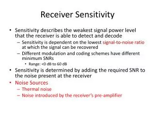
Receiver Noise and Sensitivity. Abdul Rehman. Receiver Noise. • Optical receivers convert incident optical power. into electric current through photodiode. • The relation I p = R ⋅ P in assumes that such a. conversion is noise free but this is not true even

E N D
Receiver Noise and Sensitivity Abdul Rehman
Receiver Noise • Optical receivers convert incident optical power into electric current through photodiode • The relation I p = R ⋅ Pin assumes that such a conversion is noise free but this is not true even for a perfect receiver • Two fundamental mechanisms are – Shot noise – Thermal noise • This causes fluctuations in the current even when the incident optical power has a constant power. Additional noise is generated if input power is fluctating
Photocurrent average P I p = R ⋅ Pin t • This relation still holds good if we consider photocurrent as the average current • Electrical noise induced by current fluctuations affects the receiver performance
4.4 RECEIVER NOISE Shot noise Thermal noise I p = R ⋅ Pin SNR 4.4.1 Noise mechanisms 4.4.1.1 Shot noise Spectral Density: It is often called simply the spectrum of the signal. Intuitively, the spectral density captures the frequency content of a stochastic process and helps identify periodicities Average current
Ip Constant optical power I (t ) = I p + i s (t ) is(t) I p = RPin is(t) stationary random process Poisson statistics Gaussian Wiener-Khinchin theorem is (t )is (t + τ) = Autocorrelation function t ∞ S S(f e i2 πfτdf Spectral density ) ∫ −∞
Theory Of Stochastics Process • In a stochastic or random process there is some indeterminacy • in its future evolution described by probability distributions. • This means that even if the initial condition (or starting point) • is known, there are many possibilities the process might go to, • but some paths may be more probable and others less so.
THEORY OF POISSON STATISTICS • A sequence of independent random events is one in which the occurrence of any event has no effect on the occurrence of any other. One example is simple radioac-tive decay such as the emission of 663 KeV photons by a sample of 137Cs. In contrast, the fissions of nuclei in a critical mass of 235U are correlated events in a ‘chain re- action" in which the outcome of each event, the number of neutrons released, affects the outcome of subsequent
Negative Frequency • The concept of negative frequency is purely mathematical. • This can be easily proven by some simple trigonometric math. • However in comms systems the 'negative' frequencies is simply • copies of you signal symetric about the sampling frequency. • Thus if you sample (for the carrier) at 433MHz and your data sits • at 433.1MHz then you see an image at 432.9Mhz as well. • If you move this to the 0Hz point negative frequencies • needs to be used.However, as mentioned negative frequency is not a physical • phenomenan. Imagine a sime wave of -100Hz - I can't.
SS(f) White noise Two-sided qIp f One-sided 2qIp f Noise variance τ=0 δ2 = i 2 (t ) = ∞ ∫ S s (f )df −∞ = 2qI p ∆f s s
SS(f) SS(f) 2qIp qIp f f −∆f ∆f ∆f 0 effective noise bandwidth At output of photodiode: bandwidth of photodiode Input to decision circuit: bandwidth of receiver Amp Preamp Photodiode Filter S s(f ) = 2qI p HT (f ) HT (f ) 2 One − sided ∞ = ∫ 2qI p HT (f ) 0 ∞ = 2qI p ∫ HT 0 (f ) 2 df 2 df 2 σs
d ∞ = ∫ HT 0 (f ) 2 df ∆f Stray light ⎫ Thermal generation ⎭ ⎬ ⇒ dark current (also shot noise ) σ 2 = 2q (I p + I d )∆f can be reduced by low pass filter 4.4.1.2 Thermal noise Random thermal motion of electrons in RL IT(t) s Ip is iT CT RL
Thermal noise I (t ) = I p + I s (t ) + I t (t ) thermal iT(t): stationary Gaussian random process flat up to ∼ 1THz 2k BT RL kB=1,38⋅10-23 J/K ST (f ) = (Two − sided ) ∞ ∫ S T (f )df −∞ σT = i T2 (t ) = 2 ∆f −∫f 2k BT R L 4k BT ⋅ ∆f R L df = σT independent of I p 2 = ∆ ∞ ∫ HT (f ) 0 2 ∆f = df
Also thermal noise from pre-amp field effect bipolar Amplifier noise figure 2 4k BTFn ∆f R L ⎬ : independent random processes (Gaussian ) σT = i s (t ) ⎫ iT (t )⎭ Total variance σ = σ s + σT = 2q (I p + I d )∆f + 4k BTFn ∆f R L 2 2 2
4.4.2 p-i-n Receivers SNR Neglect CT: Ip iT is RL I p 2 R 2Pin2 • 2q (RPin + I d ) ∆ f + SNR = 2 = Thermal limit 4 k BTFn ∆f RL σ R 2Pin2 • 4k BTFn ∆ f RL R 2Pin2R L • 4k BTFn ∆ f SNR ∝ Piin2 SNR ∝ R L (C L neglected ) SNR ≈ =
NEP: Noise Equivalent Power RLR 2Pin2 4k BTFn ∆f = 1 Pin2 4k BTFn ∆f RLR 2 = Pin ∆f 4k BTFn RLR 2 hν ηq 4k BTFn RL NEP = = = Pin = NEP ⋅ ∆f σs>>σT Shot noise limit • σ s = 2q (I p + I d )∆f = 2q (RPin+ I d ) ∆ f Increases linearly with Pin Obtained for large Pin Id neglected 2
ηq hν Pin • 2q ∆ f R 2Pin2 • 2qRPin ∆ f RPin • 2q ∆ f SNR ≅ = = ηPin 2hν∆f = SNR ∝ Pin Shot noise limit t −∫ h tt d w '(= = ) 1 E p = Pin TB E p = Area in a bit p d h '(t = ) 1 − ∞ h d T T = = −
Pin B E p E p = PinT B = = N p hν Pin = BE p = BN p hν B 2 ∆f = (Nyquist ) Piin = 2∆f ⋅ N p hν η ⋅ 2∆f ⋅ N p hν 2hν∆f SNR ≅ = ηN p Shot noise limit η≅1 Np=100 SNR=100 SNRdB=10log10SNR=10⋅log100 dB=20dB Np≈1000 Thermal noise dominates
4.4.3 APD Receivers Higher SNR (for same Pin) Ip=MRPin=RAPD ⋅Pin Also multiplication noise Thermal noise the same Shot noise changes due to multiplication M is a random variable p − i − n diode APD Excess noise factor F A = k A M + (1 − k A )⎜ 2 − ⎝ σ 2 = 2q (RPin + I d )∆f σ s = 2qM 2F A (RPin + I d )∆f 1 ⎞ M ⎠ s 2 ⎛ ⎟ αh αe αe αh Electrons initiate and Holes initiate and k A = k A = αe > αh αh > αe
1 M k A = 0 k A = 1 F A = 2 − F A = M Fig. 4.14 Small kA best (MRPiin ) 2qM F A (RPin + I d )∆f I p σ s + σT 2 2 SNR = = 4k BTFn ∆f RL 2 2 2 +
Thermal noise limit M 2R 2Pin2 4 k BTFn ∆f RL RLR 2 4k BTFn ∆f SNR ≅ M 2Pin2 = improved by M 2 Shot noise limit M 2R 2Pin2 2qM F ARPin ∆f RPin 2qF A ∆f SNR ≅ = 2 ηq hν Pin 2qF A ∆f ηPin 2hνF A ∆f = = reduced by F A There is optimum Mopt that maximizes SNR
M (RPin ) 2q (RPin + I d )∆f ⋅ M ⎢k A M + (1 − k A )⎜ 2 − 2 2 SNR = ⎡ ⎛ ⎞⎤ 1 M 4 k BTFn ∆f RL 2 ⎥ + ⎠⎦ ⎝ ⎣ AM 2 B [k AM 3 + (1 − k A )(2M 2 − M )]+ C = B [k AM + (1 − k A )(2M − M )]+ C }2AM − AM B [3k AM2 + (1 − k A )(4M − 1)] = 0 3 2 A A SNR = { dSNR 3 2 2 2 {B [k M + (1 − k )(2M − M )]+ C } dM {B [k M 3 + (1 − k A )(2M 2 − M )] + C }2 − MB [3k A M 2 + (1 − k A )(4M − 1)] = 0 A M 3 (Bk A − B 3k A ) + M 2 [B (1 − k A )4 − B (1 − k A )4] + M [− B (1 − k A )2 + B (1 − k A )] + 2C = 0 Bk A M 3 + B (1 − k A )M − 2C = 0 2
2 4k BTFn ∆f 2q (RPin + I d )∆f 2C B k A M + (1 − k A )M = RL 3 = 4k BTFn qRL (RPin + I d = ) 1.55 µm APD receiver: RL=1kΩ Fn=2 R=1A/W Id=2nA Fig. 4.15 Pin (dBm)
Neglect (1-kA)M: 1 ⎛ 4k BTFn ⎞ 3 = ⎜ M opt ⎜ k AqRL (RPin + I d ) ⎟ critical ⎠⎝ Mopt≈100 Mopt ≈10 Si APD: GaInAs APD: kA<<1 kA ≈0,7
4.5 RECEIVER SENSITIVITY BER BER ≤ 10−9 Sensitivity : Prec ⇒ BER = 10− 9 4.5.1 Bit-Error Rate PDF ! !
⇒ ⇒ I>ID I<ID bit 1 bit 0 I<ID I>ID for bit 1⇒ for bit 0⇒ error error p(1): p(0): probability of receiving 1 probability of receiving 0 P(0/1): probability of deciding 0 when 1 is received P(1/0): probability of deciding 1 when 0 is received BER = p (1) ⋅ P (0 / 1) + p (0) ⋅ P (1 / 0) p (1) = p (0) = BER = [P (0 / 1) + P (1 / 0)] Thermal noise: Gaussian, zero mean, variance σT2 1 2 1 2
Shot noise: p − i − n : Gaussian , zero mean , Gaussian ?, zero mean , σ2 =2q (I p + I d )∆f σs = 2qM 2F A (RPin + I d )∆f s APD : 2 σ2 = σT + σ2 bit 1 and 0 have different average value and variance 2 s bit − 1 : bit − 0 : 2 σ1 σ2 0 (I −I 1 )2 2σ1 I D −∞ σ1 1 2π − 2 ∫ P (0 / 1) = e dI (I −I 0 )2 2 σ2 ∞ I∫ σ 1 − P (1 / 0) = e dI 0 2π 0 D
I D − I1 2σ1 ∫ −∞ 1 σ1 2π −y 2 P (0 / 1) = e 2σ1dy I D − I1 2σ1 ∫ e −∞ ∞ ∫ e I1 − I D 2σ1 1 2 2 π 1 2 2 −y 2 −y dy = ⋅ 2 π dy = ⋅ 1 I 1 −I D 2σ1 = erfc 2 I − I 0 2σ0 dI 2σ0 y = dy =
∞ ∫ I D − I 0 2σ 0 1 σ 0 2π −y 2 2σ 0dy P (1 / 0) = e ∞ 1 2 −y 2 1 = ⋅ e dy = erfc 2 π I D − I 0 2 2σ 0 BER = erfc + erfc ∫ I D −I 0 2σ 0 I D −I 0 2σ0 [ ] 1 I 1 −I 0 4 2σ1
σ0 σ1 I0 ID I1 P(1/0) P(0/1) minimum for: BER = [P (0 / 1) + P (1 / 0)] 1 2 (I D −I 0 )2 2 σ2 (I D −I 1 )2 2 σ1 1 σ0 2π 1 σ1 2π − − 2 e e = 0
(I D − I 0 )2 2σ0 (I D − I 1 )2 2σ1 + ln σ0 + = + ln σ1 + 2 2 (I D − I 0 )2 (I 1 − I D )2 2σ0 2σ1 = + ln σ1 − ln σ0 2 2 (I D − I 0 )2 (I 1 − I D )2 σ0 σ1 σ1 (I 1 − I D )2 σ0 σ1 = + 2 ln ≈ 2 2 2 I D − I 0 σ0 I 1 − I D σ1 = Q = σ0I 1 − σ0I D = σ1I D − σ1I 0 σ0I 1 + σ1I 0 = I D (σ0 + σ1 )
σ 0I 1 + σ 1I 0 σ 0 + σ 1 σ1 =σ0 ⇒ I D = σ0 I 1 +σ0 I 0 I 1 + I 0 2σ0 2 I D = = Holds for p-i-n receivers, where σT2>>σS2 I D − I 0 σ0 I 1 − I D σ1 For = Q = Q 2 Q ⎤ 1 2 ⎥ = 2 erfc Q 2 1 ⎡ BER = ⎢erfc + erfc 4 ⎣ ⎦ σ0I 1 + σ1I 0 σ0 + σ1 σ1 I 1 − σ0I 1 + σ1I 1 − σ0I 1 − σ1I 0 σ1 (σ0 + σ1 ) I 1 − I D σ1 Q = = = I 1 − I 0 σ1 + σ0 =
1 x π − x 2 erfc ≅ e x >> 1 Q 2 2 Q 1 1 1 − BER = erfc 2 e ≈ ⋅ 2 2 Q 2 π Q 2 2 1 2πQ − e = Reasonable for Q>3 Q = 6 ⇒ BER ≈ 10−9
4.5.2 Minimum Average Received Power Assume: I0=0 (P0=0) I1 = MRP1 = 2MRPrec Prec = (P1 + P0 ) = P1 2 2 σ1 = σS + σT 1 1 2 2 2 σ0 = σT , 2 2 no short noise variance -- '0' bit σS = 2qM 2 FA (RP1 + Id )∆f ≅ 2qM 2 FA R2Prec ∆f 2 4k B TFn ∆f R L σT = 2 I 1 − I 0 σ1 + σ0 2MRPrec σS + σT + σT I 1 σ1 + σ0 Q = = = 2 2
Q 2 1 BER = erfc 2 BER Q Prec ⇒ ⇒ Q σ S + σT2 + Q ⋅ σT = 2MRPrec Q σ S + σT2 = 2MRPrec − Q ⋅ σT 2 2 2MRPrec Q σ S + σT2 = − σT 2 2 ⎛ 2MRPrec ⎞ 4MRPrec σT Q σ S + σT = ⎜ ⎝ ⎠ + σT − 2 2 2 ⎜ Q 4MRPrec σT Q 4M 2R 2 Q 2 2qM F AR 2Prec ∆f = Prec − 2 2
MR Q σT Q Prec = qMF A ∆f + 2 Q 2 MR Q 2 σT MR Q Prec qMF A ∆f + = ⋅ Q ⎛ σ ⎞ Prec = ⎜QqFA ∆f + T M ⎠ R ⎝ p-i-n receiver M=1, σT dominates Q Q R 4k BTFn ∆f RL ∝ B Prec ≈ σT = R
R = 1 A /W σT = 0,1 µA Q = 6 (BER = 10− 9 ) Numerical example 6 Prec ≈ ⋅ 0,1 ⋅ 10−6W = 0,6 µW 1 0,6 ⋅ 10−6 10−3 dBm Prec dBm = 10 log 6 ⋅ 10−4 dBm = 10 log = −32,2 dBm APD receiver: σT ⎞ M ⎠ Q ⎛ Prec = ⎜QqF A ∆f + ⎟ R ⎝ If σT dominant ⇒ Prec reduced by factor M But also shot noise contributes F A = k AM + (1 − k A )⎜ 2 − ⎟ ⎝ ⎛ 1 ⎞ M ⎠
⎞⎤ σT ⎫ ⎠⎦ M ⎭ ⎧ ⎨Qq∆f ⎩ Q R ⎡ ⎛ 1 ⎢k AM + (1 − k A )⎜ 2 − M Prec = ⎟⎥ + ⎬ ⎝⎣ Optimum M = ⎨Qq∆f ⎢k A + (1 − k A )⎜ + 2 ⎟⎥ − 2 ⎬ = 0 Qq∆f [k AM 2 + (1 − k A )] − σT = 0 dPrec Q ⎧ ⎡ ⎛ 1 ⎞⎤ σT ⎫ dM R ⎩ ⎝ M ⎠⎦ M ⎭ ⎣ σT Qq∆f + (1 − k A ) = k AM 2 σT Qq∆f − (1 − k A ) k AM = 2 1 ⎡ σT ⎤ k A ⎢Qq∆f + k A − 1⎥ M = 2 ⎣ ⎦
σT Qq∆f 1 k A M opt = + k A − 1 σT Qq∆f σT k AQq∆f 1 k A ≈ = Qq∆f [k AM opt + (1 − k A )]− σT = 0 2 ⎡ ⎤ σT M opt 1 M opt ⎢k AM opt + (1 − k A ) ⎢ = Qq∆f ⎥ ⎥ ⎣ ⎦
Q ⎧ 1 ⎤ ⎫ ⎥ ⎬ M opt ⎦ ⎭ ⎡ ⎛ ⎢ k A M opt + (1 − k A ) ⎜ 2 − ⎢ ⎝ 1 ⎞ ⎤ ⎡ ⎪ ⎟ ⎥ + Qq∆f ⎢ k A M opt + (1 − k A ) ⎠ ⎦ ⎣ = ⎨Qq∆f R ⎪ Prec ⎜ M opt ⎟ ⎥ ⎢ ⎥ ⎪ ⎣ ⎩ σ by replacing back the value of T = Qq∆f ⎡ 2k A M opt + 2 (1 − k A )⎤ R M Q ⎣ ⎦ 2Q 2 q∆f R ⎡ k A M opt + 1 − k A ⎤ = ⎣ ⎦ 2Q 2 q∆f ⎡ k A σ T R Qq∆f Ideal receiver ⎤ + 1 − k A ⎥ ⎦ = ⎢ ⎣ M = 1, F A = 1 σT = 0, Q Q 2 R Prec = Qq∆f = R q∆f Np: number of photons in a 1-bit
Thermal noise limit σ0 = σ1 I 0 = 0 I1 −I0 I1 σ1 + σ0 2σ1 Q = = I 12 σ1 SNR = = 4Q 2 BER = 10−9 Q = 6 ⇒ 2 SNR = 4 ⋅ 36 = 144 SNRdB = 10 log144dB = 21,6dB Shot noise limit σ0 = 0 σ1 = σS I 0 = 0
I 1 − I 0 I 1 σ 1 + σ 0 σ 1 Q = = I 12 SNR = 2 = Q 2 = 36 SNRdB = 10 log 36 = 15,6dB (peak power basis ) σ 1 SNR = ηN p (shot noise limit) Q = SNR = ηN p
ηN p 2 Q 1 1 BER = erfc 2 = erfc 2 2 η = 1 BER = 10− 9 or Q = 6 N p = Q 2 = 36 In practice Np≈1000, limited by thermal noise
4.5.3 Quantum Limit of Photodetection 1 ηN p BER = erfc assumes Gaussian statistics Shot noise limit 144424443 2 Small number of photons in a bit Poisson statistics Np.: average number photons in a bit 1 Probability of generating m electron-hole pairs m N p m! −N p Pm = e 1 BER = [P (0 / 1) + P (1 / 0)] 2
P (1 / 0) = 0 because N p = 0 for bit 0 N p 0! 0 P (0 / 1) = −N p −N p e = e for bit 1 1 −N p BER = e 2 1 −N p BER = e 2 = 10−9 − ln 2 − N p = −9 ln10 N p = 9 ln10 − ln 2 = 20,03 ≈ 20
Quantum limit: Each 1-bit must contain 20 photons: N p hν TB P1 = = N p hνB N p 2 P1 + P0 2 1 Prec = = P1 = hνB = N p hνB 2 N p 20 2 2 N p = = 10 average number of photons per bit = Numerical example λ = 1,55 µm c 3 ⋅ 108 m s 3 ⋅ 1014 Hz ν = = = λ 1,55 ⋅ 10−6 m 1,55 = 1,94 ⋅ 1014 Hz ≈ 2 ⋅ 1014 Hz = 200.000GHz = 200THz hν = 6,626 ⋅ 10−34 Js ⋅ 1,94 ⋅ 1014 s −1 = 12,85 ⋅ 10−20 J = 1,285 ⋅ 10−19 J
B = 1Gbit / s Prec = 10 ⋅ 1,285 ⋅ 10−19 ⋅ 109W = 1,285 ⋅ 10−9W 1,285 ⋅ 10−9 10 Prec ,dBm dBm = −58,9dBm = 10 log −3 In practice:20dB more power is required 10⋅100=1000 photons per bit
4.6 RECEIVER DEGRADATION So far: Noise only degrading mechanism Ideal sensitivity Practice: More power needed. Power penalty! Several sources:Extinction ratio Intensity noise (in transmitter) Timing jitter 4.6.1 Extinction Ratio Energy carried by 0-bits Laser biased above threshold P0 P1 P0>0 rex = P1 P0 1 0 1 1
Find power penalty I 1 − I 0 σ 1 + σ 0 Q = I 1 = RP1 I 0 = RP0 P1 + P0 2 R (P1 − P0 ) (P1 − P0 ) R (P1 + P0 ) σ1 + σ0 P1 + P0 σ1 + σ0 1 − rex R ⋅ 2Prec 1 + rex σ1 + σ0 Prec = Q = = = ⋅
σ1 ≈ σ0 = σT p-i-n receiver: 1 − rex R ⋅ 2 ⋅ Prec 1 − rex RPrec 1 + rex 2σT 1 + rex σT Q = ⋅ = ⋅ 1 + rex σT Q 1 − rex R Prec (0) = Prec (rex ) 1 + rex Prec (0) 1 − rex Prec (rex ) = increases with rex ⋅ σT Q R δex = = 1 + rex 1 − rex dB Power penalty δex ,dB = 10 log
Fig. 4.18 rex rex≈0,05 Laser biased below threshold: 1 + 0,05 0,95 dB = 0,43dB δex ,dB = 10 log δex,dB significant Laser biased above threshold: APD receiver: Power penalty larger by factor of 2 for same rex