Download
1 / 17
170 likes | 216 Views
Explore the concepts of AC circuits, impedance, and parallel resonance in this informative e-course session from Fairfield University. Learn about filters, transformers, and impedance matching in this comprehensive module. Understand how capacitive and inductive reactance affect parallel circuits and how to calculate impedance in resonant circuits. Dive into the world of tank circuits, resonance bands, and Q factor adjustments. Prepare for the upcoming session with a detailed schedule and study materials. Join the session for a deep dive into Basic Electricity concepts!

E N D
Parallel Resonance Session 4c for Basic ElectricityA Fairfield University E-CoursePowered by LearnLinc Basic Electricity
Module: Basic Electronics(AC Circuits and Impedance: two parts) • Text: “Electricity One-Seven,” Harry Mileaf,Prentice-Hall, 1996, ISBN 0‑13‑889585‑6 (Covers much more material than this section) • References: • “Digital Mini Test: Principles of Electricity Lessons One and Two,” SNET Home Study Coordinator, (203) 771-5400 • Electronics Tutorial (Thanks to Alex Pounds) • Electronics Tutorial (Thanks to Mark Sokos) • Basic Math Tutorial (Thanks to George Mason University) • Vector Math Tutorial (Thanks to California Polytec atatom.physics.calpoly.edu ) • Alternating Current and Impedance • 5 on-line sessions plus one lab • Resonance and Filters • 5 on-line sessions plus one lab Basic Electricity
Section 4: AC, Inductors and Capacitors • 0BJECTIVES:This section discusses AC voltage / current and their effects on parallel circuit components (resistors, inductors, transformers and capacitors). The concept of resonance and its use to produce filters is also described. Basic Electricity
Section 4 Schedule: Session 4a – 07/08Session 4b – 07/10 (break for a week) Session 4c – 07/22 Session 4d – 07/24(lab - Postponed) Session 4e – 07/29 (Quiz 4 due 08/12)Session 4f – 08/12 08/14 08/17 Parallel L-C Circuits Parallel R-L-C Circuits (no class on 07/15 or 07/17) Parallel ResonanceTuning and Filters Transformers and Impedance MatchingReview (Discuss Quiz 4)MT2 ReviewMT2 – AC Circuits Text 4.114 – 4.122Text 4.123 – 4.132Text 4.133 – 4.146Text 4.147 – 4.153Text 4.154 – 4.160 Basic Electricity
(Parallel R-L-C) Review • Capacitive reactance XC = 1/2fC at -90º • Inductive reactance XL = 2fL at 90º • Impedances in parallel add as inverses • Break the problem down into two simple problems • First combine the Inductive and Capacitive branches • Here the vectors are in opposite directions; they just subtract. • Inductive reactance points up (90º); the inverse points down • Capacitive reactancepoints down (-90º); the inverse points up • The larger of the two inverses dominates • Now add in the inverse of the resistive branch • Find the magnitude (lengths) by using the square root of the sum of squares • Find the phases as the angle who’s tangent is the vertical / horizontal • Now just invert again to get the total parallel impedance Basic Electricity
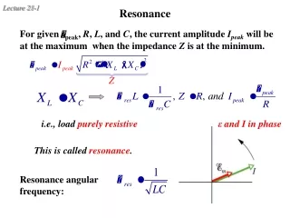
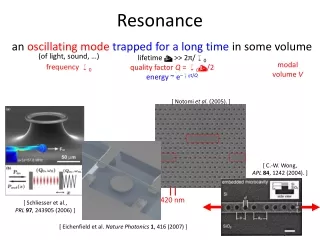
Resonance • XL and XC cancel • Parallel Resonance • High Impedance • Low line current (high current in the LC loop!) • Series Resonance • Low impedance • High line current • Resonant frequency2fL = 1/2fCf = 1/2(LC)½ Basic Electricity
The Tank Circuit • A “tank” circuit “rings” like a bell Basic Electricity
Current at Resonance • At Resonance (for an Ideal parallel RC) • |IL| = |IC| but they are in opposition • ILine = IL + IC = 0 Basic Electricity
Impedance at Resonance • At Resonance (for an Ideal parallel RC) • |XL| = |XC| but they are in opposition • 1/Z = 1/XL + 1/XC = 1/Z is very large near resonance! Basic Electricity
Line Current off Resonance • If |IL| < |IC| the line current is capacitive • If |IL| > |IC| the line current is inductive Basic Electricity
Impedance off Resonance • If |XL| > |XC| the impedance is capacitive • If |XL| < |XC| the impedance is inductive • Line Impedance • 1/Z = 1/XL + 1/XC Basic Electricity
Real Tank Circuits • Inductors have a series resistance; not a parallel one Basic Electricity
A Parallel RLC Example • First invert the series RL1/Z1 = 1/(500º + 20090º) = 1/[(502 +2002)½arctan(200/50) = 1/[(502 +2002)½arctan(200/50) = 1/(206.276º) = 0.00485-76º1/Z2 = 1/(200-90º)1/Zt = 0.00485-76º + 0.00590º= .00485*cos(76)0º+.00485*sin(-76)90º + .00590º= 0.001170º + 0.000390º = 0.001214.4º Zt = 833-14.4º Basic Electricity
The Resonance Band • Changing the Inductor’s series resistance changes the “Bandwidth” Basic Electricity
“Q” • Q = XL / R = XC / R at resonance Basic Electricity
Changing Q • Adding a parallel (shunt) resistor lowers Q • More resistance in tank loop lowers Q Basic Electricity
Section 4 Schedule: Session 4a – 07/08Session 4b – 07/10 (break for a week) Session 4c – 07/22 Session 4d – 07/24 (lab - Postponed) Session 4e – 07/29 (Quiz 4 due 08/12)Session 9 starts – 08/05Session 4f – ?? ?? ?? Parallel L-C Circuits Parallel L-R-C Circuits(no class on 07/15 or 07/17) Parallel Resonance Tuning and FiltersTransformers and Impedance MatchingBusiness Writing Review (Discuss Quiz 4)MT2 ReviewMT2 – AC Circuits Text 4.114 – 4.122Text 4.123 – 4.132Text 4.132 – 4.146 Text 4.147 – 4.153Text 4.154 – 4.160 Basic Electricity