Download
1 / 17
200 likes | 246 Views
Review of concept selection, airfoil, geometry, and layout for Phoenix Aerospace AAE 451 project in Fall 2001, with detailed aerodynamic analysis and constraint review. Includes airfoil comparison, geometry selection, and key design considerations.

E N D
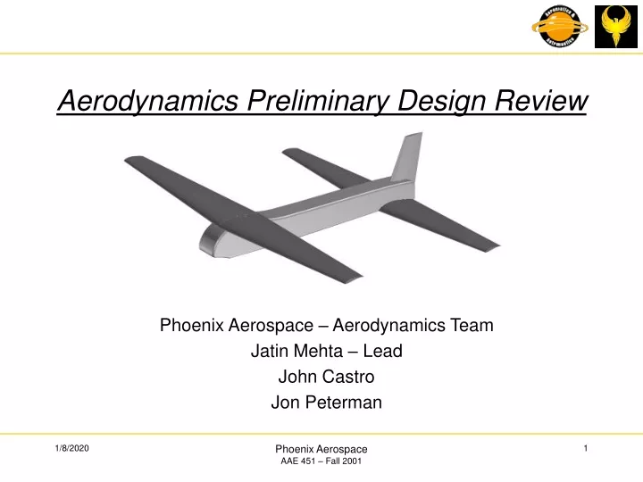
Aerodynamics Preliminary Design Review Phoenix Aerospace – Aerodynamics Team Jatin Mehta – Lead John Castro Jon Peterman Phoenix Aerospace AAE 451 – Fall 2001
Objectives • Concept selection & constraint analysis review • Preliminary selection of airfoil, geometry, & aircraft layout • Airfoil • Aspect Ratios • Taper • Sweep • Span • Chord • Wing & tail location • Preliminary aerodynamic analysis • Whole Aircraft CL & CD • Cruise a & drag estimates Phoenix Aerospace AAE 451 – Fall 2001
Constraint analysis • Constraint analysis review • Turn rate constraint is correct • Design constrained by turn rate for high turn speeds (Vturn = Vloiter) • Design constrained by Ground Roll & Climb rate for lower turn speeds (Vturn = 20 ft/s) • Vturn = 25 ft/s for constraint analysis Phoenix Aerospace AAE 451 – Fall 2001
Constraint Analysis • Original Constraint Diagram • Modified Constraint Diagram • Modified constraint allows for an increased power loading • Smaller propulsion system required to meet requirements (P30=0.422Hp P25=0.182Hp) Phoenix Aerospace AAE 451 – Fall 2001
Airfoil, Geometry, & Layout Selection • Airfoil Selection • 25 Airfoils considered • Compared airfoils using: • Clmax, Cla • Drag Polar (design point of W/S=0.58) • CL= (1/q)(W/S) = 0.55 ~ Cl • Manufacturing & structural considerations (thickness & trailing edge shape) • Current analysis uses same airfoil for both wings • Selig S1210 airfoil selected • L/Dmax = 74.5 • Clmax = 1.82 • Cdmin = 0.0138 • Max Thickness = 12.1% • Selig S1210 Phoenix Aerospace AAE 451 – Fall 2001
Airfoil, Geometry, & Layout Selection Selig S1210 • Cl vs. a • Selig S1210 shows large Clmax advantage over other airfoils studied • Cla approximately the same for all airfoils Phoenix Aerospace AAE 451 – Fall 2001
Airfoil, Geometry, & Layout Selection Selig S1210 • Cl vs. Cd • S1210 has higher Cdmin • However the L/Dmax is the highest of all considered airfoils Phoenix Aerospace AAE 451 – Fall 2001
Concept, Airfoil, Geometry, & Layout Selection • Tandem wing concept chosen • Slight increase in required analysis • Concept has good overall characteristics for mission • No major problems with concept • Added market value due to unique design • Geometry Selection • Geometries selected using historical data & trends from Raymer • SAE, ICAS, & industry papers on tandem wing & canard configurations used for tandem wing sizing properties • Aspect Ratio, AR • Feistel, et al, SAE paper shows that the forward wing should be at a higher aspect ratio than the rear wing to allow the front wing to stall first • Aspect ratios chosen from historical data and structural concerns • ARFW = 8 ARRW = 7 • Detailed analysis of configuration may change AR Phoenix Aerospace AAE 451 – Fall 2001
Airfoil, Geometry, & Layout Selection • Sweep (1/4 chord), L • No sweep is desirable for low speed flight, cruise, and takeoff & landing (Raymer, pg. 61) • Taper Ratio, l • Historical data and trends from Raymer used to choose taper ratio • Taper ratio required to approximate elliptical lift distribution (Raymer, pg. 64) • Wing sweep effects on taper ratio were also taken into account (Raymer, pg. 65) • Taper ratio for both wings = 0.45 • Taper ratio may not be used depending on construction technique and material choice • Span & Chord, b & c • Span and chord calculated using design area, aspect ratio, and area ratio • bwing = (Swing * ARwing)2 • cavg,wing = Swing / bwing Phoenix Aerospace AAE 451 – Fall 2001
Airfoil, Geometry, & Layout Selection • Dihedral • Dihedral chosen using estimates in Raymer for high wing (pg. 68) • 3o Dihedral chosen for both wings • Wing Separation / Location • Feistel, et al, SAE paper shows that the front and rear wing should be separated vertically and horizontally as much as possible (Vsep ~ 0.5*cavg Xsep as large as possible) • Vsep = 6 in • Xsep = 4 ft • Vertical Tail Sizing & Location • Tail sized using historical data (previous AAE 451 classes) • Will be updated with Stability & Control calculations Phoenix Aerospace AAE 451 – Fall 2001
Geometry & 3 View Phoenix Aerospace AAE 451 – Fall 2001
Geometry & 3 View Phoenix Aerospace AAE 451 – Fall 2001
Geometry & 3 View Phoenix Aerospace AAE 451 – Fall 2001
Aerodynamic Analysis Phoenix Aerospace AAE 451 – Fall 2001
Aerodynamic Analysis Phoenix Aerospace AAE 451 – Fall 2001
Aerodynamic Analysis • **************** Front Wing Summary **************** • Front Wing Area (ft2) = 4.42 • Front Wing Span (ft) = 5.94 • Front Wing Average Chord (in) = 8.91 • Front Wing Root Chord (in) = 12.30 • Front Wing Tip Chord (in) = 5.53 • Front Wing Spanwise Efficiency = 0.89 • Front Wing 3D CLalpha (1/deg) = 0.0718 • ------------------------------------------------------ • ***************** Rear Wing Summary ***************** • Rear Wing Area (ft^2) = 4.42 • Rear Wing Span (ft) = 5.56 • Rear Wing Average Chord (in) = 9.53 • Rear Wing Root Chord (in) = 13.14 • Rear Wing Tip Chord (in) = 5.92 • Rear Wing Spanwise Efficiency = 0.88 • Rear Wing Standalone 3D CLalpha (1/deg) = 0.0698 • Rear Wing Downwash effect = 0.0956 • Rear Wing 3D CLalpha (1/deg) = 0.0631 • ------------------------------------------------------- *************** Whole Aircraft Summary *************** Whole Aircraft 3D CLalpha (1/deg) = 0.1349 Whole Aircraft CLmaxTO = 2.29 Whole Aircraft 3D CD = 0.0380 Phoenix Aerospace AAE 451 – Fall 2001
Airfoil, Geometry, & Layout Selection • The larger the Cla, the greater the losses due to 3-Dimensional effects • Cla for compared airfoils was constant, thus not a large driver of airfoil selection Phoenix Aerospace AAE 451 – Fall 2001