Download
1 / 11
110 likes | 233 Views
Calibration of LIGO data in the time domain. X. Siemens, B. Allen, M. Hewitson, M. Landry. -So far LIGO data has been calibrated in the frequency domain. -For the S1 analysis 60s Fourier transforms were used. The change in the response of the instrument was computed every minute.

E N D
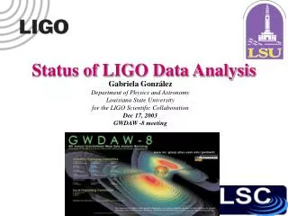
Calibration of LIGO data in the time domain X. Siemens, B. Allen, M. Hewitson, M. Landry
-So far LIGO data has been calibrated in the frequency domain. -For the S1 analysis 60s Fourier transforms were used. The change in the response of the instrument was computed every minute. -For the S2 analysis the pulsar working group decided to use 1800s long Fourier transforms to take advantage of the speed of FFT. -GEO has been producing h(t) and we can adapt their method to calibrate our data.
[R. Adhikari et al. LIGO-T030097-00-D] We reconstruct the strain from the residual and control motions: [Mohanty and Rakhmanov, August 2003 LSC Meeting] High frequency Low frequency
Need to construct digital filters for the inverse sensing function , the servo , and the actuation function Have implemented time domain calibration for S2/H1. Sensing function -cavity pole at 84.8 Hz [Inverse of pole is unstable: Stabilise it by adding a zero at 100 kHz and filter up-sampled (by a factor of 16) Q through it] -anti-aliasing 8th order elliptic filter at 7.5KHz [Has zeros on imaginary axis which need to be moved off; Inverse rises sharply at 7.5 kHz: low-pass at 6kHz with high order BW filter] -a pole at 100kHz [We ignore it] -electronics gain Have digitised the modified sensing function using a bi-linear transformation at 16384*16Hz
Have digitised the modified sensing function using a bi-linear transformation at 16384*16Hz. Response of digital filter (blue) vs. official sensing function (red):
Servo -11 2nd order digital filters [problems with first filter: a double pole at 0Hz which we moved to 1.6Hz] Response of modified servo (blue) vs. actual servo (red):
Actuation function -13 2nd order digital filters (7 for x-arm, 6 for y-arm), pendulum transfer function, anti-imaging 4th order elliptic filter at 7.5kHz, time delay Pade filter, snubber Analog part of this filter was digitised using a bilinear transformation at 16384Hz Response of digitised actuation (blue) vs. official actuation (red): Actuation makes no difference at high frequencies! m/count Hz
Comparison of Fourier transform of time domain calibrated data (blue) with data calibrated in the frequency domain (red). ~1Hz band around 1000Hz at 1/60 Hz: Wrap-around
Around 630Hz: Around 112Hz:
Conclusions • All elements of pipeline are in place • Code has been parallelized (under condor) and full S2/H1 dataset is • calibrated on Medusa (UWM) in a few hours. The output is 16s frames. • Still need filters for H2 and L1. • Will keep working on filter and pipeline optimization.