Download
1 / 13
130 likes | 186 Views
Learn how to verify and set up CV-A1 camera AGC, including building a serial cable to connect to Gemini PC com port and installing Camera Control Tool software on Windows. Follow detailed steps for a successful setup.

E N D
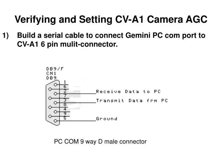
Verifying and Setting CV-A1 Camera AGC Build a serial cable to connect Gemini PC com port to CV-A1 6 pin mulit-connector. PC COM 9 way D male connector
Pin to Pin Connection • Connect PC DB9 Pin 2 to HR10A-7R-6PB Pin 1 • Connect PC DB9 Pin 3 to HR10A-7R-6PB Pin 2 • Connect PC DB9 Pin 5 to HR10A-7R-6PB Pin 3
2) Install Camera Control Tool for Windows Step on installing the software 2.1 double click on the Software_A1Uv13.zip 2.2 double click on the A1UVv13.exe
2.3 Below diagram will appear. 2.4 Below diagram will appear and click on the Next.
2.5 Below diagram will appear and click on the Next. 2.6 Below diagram will appear and click on the Next.
2.7 Below diagram will appear and click on the Next. 2.8 Installing the CV-A1 program.
2.9 Below diagram will appear and click on Finish. 3.0 Below diagram will appear on the desktop and click on the the first button and than the second button.
4.0 Below diagram will appear when you click on the first button. 5.0 Below diagram will appear when you click on the second button.
6.0 connect the hirose connector which you have solder to the camera.
7.0 connect the serial connector which you have solder to the computer serial port. Serial connector which you had solder Serial port
8.0 click on the Auto button and a dialog box will appear after it had found a camera, next just click yes. 9.0 the Status will change to on line
10.0 click on the Synchromize Program button. 11.0 check the setting on the camera control for gain setup.
12.0 click on the Synchromize Camera button. 13.0 Lastly you adjust the camera gain to check that you can adjust the lighting for the camera.