Download
1 / 9
220 likes | 846 Views
Chapter 17: Synchronous Motor. Introduction. The synchronous generators can operate either as generators or as motors. When operating as motors (by connecting them to a 3-phase source), they are called synchronous motors. Synchronous motors run in synchronism with the revolving field.

E N D
Chapter 17: Synchronous Motor Electro Mechanical System
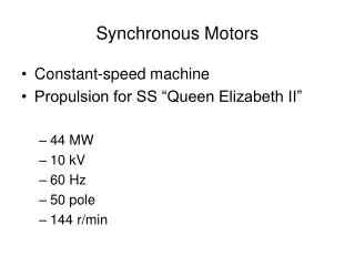
Introduction • The synchronous generators can operate either as generators or as motors. • When operating as motors (by connecting them to a 3-phase source), they are called synchronous motors. • Synchronous motors run in synchronism with the revolving field. • The speed of rotation is tied to the frequency of the source. • The motor speed stays constant, irrespective of the load or voltage of the 3-phase line. • Synchronous motors are used not so much because they run at constant speed. • They possess some unique electrical properties. • Synchronous motors are rated between 150 kW (200 hp) & 15 MW (20 000 hp) and turn at speeds ranging from 150 to 1800 r/min. • These machines are mainly used in heavy industry Electro Mechanical System
Construction • Synchronous motors are identical to salient-pole ac generators. • The stator: • It is composed of a slotted magnetic core, which carries a lap winding which is also identical to a 3-phase induction motor. • The rotor: • Has a set of salient poles excited by a dc current using two slip-rings. • It also carry a squirrel-cage winding similar to that in a 3-phase induction motor. This damper winding serves to start the motor. • Modern synchronous motors often employ brushless excitation, similar to that used in synchronous generators. Electro Mechanical System
Starting a Synchronous Motor • A synchronous motor can not start by itself • The motor is equipped with a squirrel case winding, to start it as an induction motor. • When the stator is connected to 3-phase line, the motor accelerates until it reaches slightly below synchronous speed. • The dc excitation is suppressed during this starting period. • Very large synchronous motors (20 MW and more) are sometimes brought up to speed by an auxiliary motor, called a pony motor. • Finally, in some big installations the motor may be brought up to speed by a variable-frequency electronic source Electro Mechanical System
Pull-in torque • As soon as the motor is running at close to synchronous speed, the rotor is excited with dc current. This produces N and S poles around the circumference of the rotor. • If the poles on the rotor at the moment the exciting current is facing the poles of opposite polarity on the stator, a strong magnetic attraction is set up between them • The mutual attraction locks the rotor and stator poles together. • The rotor is pulled with the revolving field. Torque develop at the moment is called pull-in torque. Electro Mechanical System
Pull-in torque • dc current must be applied at the right moment, otherwise a mechanical shock will be produced and the circuit breakers will trip. • The starter detects the precise moment when to apply excitation. • Once the motor turns at synchronous speed, no voltage is induced in the squirrel-cage winding and so it carries no current. • The behavior of a synchronous motor is entirely different from that of an induction motor. Electro Mechanical System
Motor under Load • At no-load conditions, the rotor poles are directly opposite the stator poles and their axes coincide • As mechanical load is applied, the rotor poles fall slightly behind the stator poles, but continues to turn at synchronous speed • Greater torque is developed with increase separation angle • There is a limit when the mechanical load exceeds the pull-out torque; the motor will stall and come to a halt • The pull-out torque is a function of the dc excitation current and the ac stator current Electro Mechanical System
Under load-simple calculations • Equivalent circuit represents one phase of a wye-connected motor. It is identical to the equivalent circuit of an ac generator. • The flux created by the rotor induces a voltage EO in the stator. It depends on the dc exciting current Ix. EO varies with excitation. • Rotor and stator poles are lined up at no-load. Induced voltage EO is in phase with the line-to-neutral voltage E. • If, we adjust the excitation so that EO = E, the motor "floats" on the line and the line current I is practically zero. • The only current needed is to supply the small windage and friction losses in the motor, and so it is negligible. Electro Mechanical System
Under load-simple calculations • If we apply a mechanical load. The motor will begin to slow down, so the rotor poles fall behind the stator poles by an angle α. • Due to this mechanical shift, EO reaches its maximum value a little later than before. EO is now δ electrical degrees behind E. • The mechanical displacement α produces an electrical phase shift δ between EO and E, which produces a difference of potential Ex across the synchronous reactance Xs given by: • Ex = E – EO • A current I must flow in the circuit, given by: jIXS = Ex • I = – j Ex /XS = – j(E – EO)/Xs • I is nearly in phase with E, so the motor absorbs active power Electro Mechanical System