Download
1 / 19
250 likes | 671 Views
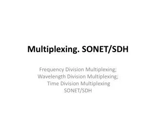
SONET/SDH Synchronous Optical Network/ Synchronous Digital Hierarchy. SONET was developed by ANSI SDH was developed by ITU-T. SONET/SDH Rates. STS- synchronous Transport Signal STM – Synchronous Transport Modules OC- optical carriers. Figure 20-1. A SONET System.

E N D
SONET/SDH Synchronous Optical Network/ Synchronous Digital Hierarchy SONET was developed by ANSI SDH was developed by ITU-T
SONET/SDH Rates STS- synchronous Transport Signal STM – Synchronous Transport Modules OC- optical carriers
Figure 20-1 A SONET System STS Mux/Demux – beginning & end points Regenerator – repeater that regenerates the optical signals Add/drop mux – add signals into a given path or remove a desired signal from a path
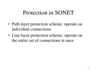
Figure 20-2 An Example of a SONET Network Section – optical link connecting 2 neighbor devices Line – portion of a network between 2 muxes Path - end to end portion of the network between 2 STS muxes
Figure 20-3 SONET Layers • Photonic Layer • Specs for optical fiber channel, sensitivity of the receiver • NRZ – 1-presence of light • Section layer • Responsible for the movement of a signal across a physical section • Framing, scrambling, error control • Line layer • - STS mux and add/drop mux provide line layer functions • Path layer • Responsible for the movement of signal from its optical source to its optical destination • Transformation of signals • STS mux provides path layer functions
Figure 20-4 Device-Layer Relationship in SONET
Figure 20-5 Data Encapsulation in SONET
Figure 20-6 STS-1 Frame
Figure 20-7 STS-1 Frame Overhead SPE – Synchronous payload envelope - Contains user data and details about charges (if any) Path overhead - end-to-end tracking information
Figure 20-8 STS-1 Frame Section Overhead A1 & A2 – for framing & synchronization, F6 & 28 in hex C1 – Frame id B1 – LRC E1 –used for communication bet. regenerators or bet. terminals & regenerators F1 reserved for user needs D1, D2, D3 – for operation, administration and maintenance signaling
Figure 20-9 STS-1 Frame Line Overhead H1, H2, H3 – identify the location of the payload in the frame K1, K2 – used for automatic detection of problems in line-terminating equipment (mux) Z1, Z2 – reserved for future use
Figure 20-10 Payload Pointers
Figure 20-11 STS-1 Frame Path Overhead J1 – used for tracking the path C2 – path identification byte, used to identify different protocols used at higher levels G1- sent by the receiver to communicate its status to the sender F2 – reserved for user needs H4 – multiframe indicator
Figure 20-12 Virtual Tributaries - Partial payload that can be inserted into STS-1 and combined with other partial payloads to fill out the frames SONET – backward compatible with the current digital hierarchy (DS-1 to DS-3
Figure 20-13 VT Types
Figure 20-14 Multiplexing STS Frames STS-n 3 STS-1s = 1 STS-3 4 STS-3s = 1 STS-12
Figure 20-15 STS Multiplexing
Figure 20-16 ATM in an STS-3 Envelope
Can replace T-1 or T-3 lines Can be the carrier for ISDN and B-ISDN Can be the carrier for ATM cells Can support bandwidth on demand Can be used as the backbone or totally replace other networking protocols such as FDDI. Applications