Download
1 / 38
920 likes | 2.27k Views
“Insulators” Introduction. What Is an Insulator?. An insulator is a “dam***” poor conductor! And more, technically speaking! An insulator is a mechanical support! Primary function - support the “line” mechanically Secondary function– electrical Air is the insulator

E N D
“Insulators”Introduction GWCET, NAGPUR– A V WANJARI
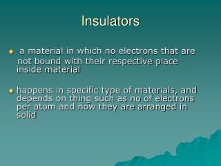
What Is an Insulator? • An insulator is a “dam***” poor conductor! And more, technically speaking! • An insulator is a mechanical support! • Primary function - support the “line” mechanically • Secondary function– electrical • Air is the insulator • Outer shells/surfaces are designed to increase leakage distance and strike distance GWCET, NAGPUR– A V WANJARI
What Does an Insulator Do? • Maintains an Air Gap • Separates Line from Ground • length of air gap depends primarily on system voltage, modified by desired safety margin, contamination, etc. • Resists Mechanical Stresses • “everyday” loads, extreme loads • Resists Electrical Stresses • system voltage/fields, overvoltages • Resists Environmental Stresses • heat, cold, UV, contamination, etc. GWCET, NAGPUR– A V WANJARI
Where Did Insulators Come From? • Basically grew out of the needs of the telegraph industry – starting in the late 1700s, early 1800s • Early history centers around what today we would consider very low DC voltages • Gradually technical needs increased as AC voltages grew with the development of the electric power industry GWCET, NAGPUR– A V WANJARI
History Approx 1840 • Glass plates used to insulate telegraph line DC to Baltimore • Glass insulators became the ”norm” soon thereafter – typical collector’s items today • Many, many trials with different materials – wood – cement – porcelain - beeswax soaked rag wrapped around the wire, etc. • Ultimately porcelain and glass prevailed GWCET, NAGPUR– A V WANJARI
History Approx 1893 - 1897 • Wet process porcelain developed for high voltage applications • Porcelain insulator industry started Approx 1902 - 1920 • Application voltages increased • Insulator designs became larger, more complex • Ceramics (porcelain, glass) still only choices at high voltages GWCET, NAGPUR– A V WANJARI
History Approx 1960 • US trials of first “NCIs” – cycloaliphatic based • Not successful, but others soon became interested and a new industry started up Approx 1960 - 1965 • Europeans develop “modern” style NCI – fiberglass rod with various polymeric sheds • Now considered “First generation” GWCET, NAGPUR– A V WANJARI
History Approx 1970 - present • NCI insulator industry really begins in US with field trials of insulators • Since that time - new manufacturers, new designs, new materials • NCIs at “generation X” – there have been so many improvements in materials, end fitting designs, etc. • Change in materials have meant changes in line design practices, maintenance practices, etc. • Ceramic manufacturers have not been idle either with development of higher strength porcelains, RG glazes, etc. GWCET, NAGPUR– A V WANJARI
History Approx 1970 - present • Domestic manufacturing of insulators decreases, shift to offshore (all types) • Engineers need to develop knowledge and skills necessary to evaluate and compare suppliers and products from many different countries • An understanding of the basics of insulator manufacturing, design and application is more essential than ever before GWCET, NAGPUR– A V WANJARI
Insulator Types • For simplicity will discuss in terms of three broad applications: • Distribution lines (thru 69 kV) • Transmission lines (69 kV and up) • Substations (all voltages) GWCET, NAGPUR– A V WANJARI
Insulator Types • Distribution lines • Pin type insulators -mainly porcelain, growing use of polymeric (HDPE – high density polyethylene), limited use of glass (in US at least) • Line post insulators – porcelain, polymeric • Dead end insulators – polymeric, porcelain, glass • Spool insulators – porcelain, polymeric • Strain insulators, polymeric, porcelain GWCET, NAGPUR– A V WANJARI
Types of Insulators – Distribution GWCET, NAGPUR– A V WANJARI
Insulator Types • Transmission lines • Suspension insulators - new installations mainly NCIs, porcelain and glass now used less frequently • Line post insulators – mainly NCIs for new lines and installations, porcelain much less frequent now GWCET, NAGPUR– A V WANJARI
Types of Insulators – Transmission GWCET, NAGPUR– A V WANJARI
Insulator Types • Substations • Post insulators – porcelain primarily, NCIs growing in use at lower voltages (~161 kV and below) • Suspension insulators –NCIs (primarily), ceramic • Cap and Pin insulators – “legacy” type GWCET, NAGPUR– A V WANJARI
Types of Insulators – Substation GWCET, NAGPUR– A V WANJARI
Ceramic Porcelain or toughened glass Metal components fixed with cement ANSI Standards C29.1 through C29.10 Non Ceramic Typically fiberglass rod with rubber (EPDM or Silicone) sheath and weather sheds HDPE line insulator applications Cycloaliphatic (epoxies) station applications, some line applications Metal components normally crimped ANSI Standards C29.11 – C29.19 Insulator Types - Comparisons GWCET, NAGPUR– A V WANJARI
Ceramic Materials very resistant to UV, contaminant degradation, electric field degradation Materials strong in compression, weaker in tension High modulus of elasticity - stiff Brittle, require more careful handling Heavier than NCIs Non Ceramic Hydrophobic materials improve contamination performance Strong in tension, weaker in compression Deflection under load can be an issue Lighter – easier to handle Electric field stresses must be considered Insulator Types - Comparisons GWCET, NAGPUR– A V WANJARI
Ceramic Generally designs are “mature” Limited flexibility of dimensions Process limitations on sizes and shapes Applications/handling methods generally well understood Non Ceramic “Material properties have been improved – UV resistance much improved for example Standardized product lines now exist Balancing act - leakage distance/field stress – take advantage of hydrophobicity Application parameters still being developed Line design implications (lighter weight, improved shock resistance) Insulator Types - Comparisons GWCET, NAGPUR– A V WANJARI
Design Criteria - Mechanical • An insulator is a mechanical support! • Its primary function is to support the line mechanically • Electrical Characteristics are an afterthought. • Will the insulator support your line? • Determine The Maximum Load the Insulator Will Ever See Including NESC Overload Factors. GWCET, NAGPUR– A V WANJARI
Design Criteria - Mechanical • Suspension Insulators • Porcelain • M&E (Mechanical & Electrical) Rating • Represents a mechanical test of the unit while energized. • When the porcelain begins to crack, it electrically punctures. • Average ultimate strength will exceed the M&E Rating when new. • Never Exceed 50% of the M&E Rating • NCIs (Polymer Insulators) • S.M.L. – Specified Mechanical Load • Guaranteed minimum ultimate strength when new. • R.T.L. – Routine Test Load – Proof test applied to each NCI. • Never Load beyond the R.T.L. GWCET, NAGPUR– A V WANJARI
Design Criteria - Mechanical • Line Post insulators • Porcelain • Cantilever Rating • Represents the Average Ultimate Strength in Cantilever – when new. • Minimum Ultimate Cantilever of a single unit may be as low as 85%. • Never Exceed 40% of the Cantilever Rating – Proof Test Load • NCIs (Polymer Insulators) • S.C.L. (Specified Cantilever Load) • Not based upon lot testing • Based upon manufacturer testing • R.C.L. (Rated Cantilever Load) or MDC or MDCL (Maximum Design Cantilever Load) or MCWL or WCL (Working Cantilever Load) • Never Exceed RCL or MDC or MDCL or MCWL or WCL • S.T.L. (Specified Tensile Load) • Tensile Proof Test=(STL/2) GWCET, NAGPUR– A V WANJARI
Design Criteria - Mechanical • Other Considerations • Suspensions and Deadends – Only apply tension loads • Line Posts – • Cantilever is only one load • Transverse (tension or compression) on line post – loading transverse to the direction of the line. • Longitudinal – in the direction of travel of the line • Combined Loading Curve – • Contour curves representing various Longitudinal loads • Available Vertical load as a function of Transverse loading • Manufacturers have different safety factors!!! GWCET, NAGPUR– A V WANJARI
Design Criteria - Electrical • An Insulator is a mechanical support! • Air imparts Electrical Characteristics • Strike Distance (Dry Arcing Distance) is the principal constituent to electrical values. • Dry 60 Hz F/O and Impulse F/O – based on strike distance. • Wet 60 Hz F/O • Some would argue leakage distance as a principal factor. • At the extremes that argument fails – although it does play a role. • Leakage distance helps to maintain the surface resistance of the strike distance. • Leakage Requirements do play a role!!! GWCET, NAGPUR– A V WANJARI
Dry Arcing Distance – (Strike Distance) – “The shortest distance through the surrounding medium between terminal electrodes….” 1 1 – IEEE Std 100 - 1992 Design Criteria - Electrical GWCET, NAGPUR– A V WANJARI
Design Criteria – Leakage Distance • What is Leakage Distance? • “The sum of the shortest distances measured along the insulating surfaces between the conductive parts, as arranged for dry flashover test.” 1 • 1 – IEEE Std 100 - 1992 GWCET, NAGPUR– A V WANJARI
Design Criteria - Electrical • What’s an appropriate Leakage Distance? • Empirical Determination • What’s been used successfully? • If Flashovers occur – add more leak? • ESDD (Equivalent Salt Deposit Density) Determination • Measure ESDD • Pollution Monitors • Dummy Insulators • Remove in-service insulators • Evaluate ESDD and select appropriate Leakage Distance GWCET, NAGPUR– A V WANJARI
Design Criteria - Electrical GWCET, NAGPUR– A V WANJARI
Design Criteria - Electrical GWCET, NAGPUR– A V WANJARI
Design Criteria - Electrical GWCET, NAGPUR– A V WANJARI
Improved Contamination Performance GWCET, NAGPUR– A V WANJARI
Improved Contamination Performance • Polymer insulators offer better contamination flashover performance than porcelain? • Smaller core and weathershed diameter increase leakage current density. • Higher leakage current density means more Ohmic Heating. • Ohmic Heating helps to dry the contaminant layer and reduce leakage currents. • In addition, hydrophobicity helps to minimize filming GWCET, NAGPUR– A V WANJARI
Improved Contamination Performance • “the contamination performance of composite insulators exceeds that of their porcelain counterparts” • “the contamination flashover performance of silicone insulators exceeds that of EPDM units” • “the V50 of polymer insulators increases in proportion to the leakage distance” CEA 280 T 621, “Leakage Distance Requirements for Composite Insulators Designed for Transmission Lines” GWCET, NAGPUR– A V WANJARI
Insulator Selection • Where do I get these values? • Leakage Distance or Creepage Distance • Manufacturer’s Catalog • Switching Surge • Wet W/S • ((Wet Switching Surge W/S)/√2) ≥ 60 Hz Wet Flashover (r.m.s.) • Peak Wet 60 Hz value will be lower than Switching Surge Wet W/S • Impulse Withstand • Take Positive or Negative Polarity, whichever is lower • If only Critical Impulse Flashover is available – assume 90% (safe estimate for withstand) GWCET, NAGPUR– A V WANJARI
Select the 69 kV Insulator shown at right. I-string – Mechanical Worst Case – 6,000 lbs Suspension: ≥ 12k min ultimate Leakage Distance ≥ 42” Switching Surge ≥ 125 kV Impulse Withstand ≥359 kV Insulator Selection GWCET, NAGPUR– A V WANJARI
Insulator Selection • Porcelain – 5-3/4 X 10” bells X 4 units GWCET, NAGPUR– A V WANJARI
Grading Rings • Simulate a larger, more spherical object • Reduce the gradients associated with the shielded object • Reduction in gradients helps to minimize RIV & TVI • Porcelain or Glass – • Inorganic – breaks down very slowly • NCIs • Polymers are more susceptible to scissioning due to corona • UV – short wavelength range – attacks polymer bonds. • Most short wavelength UV is filtered by the environment • UV due to corona is not filtered GWCET, NAGPUR– A V WANJARI
NCIs and Rings • Grading (Corona) Rings • Due to “corona cutting” and water droplet corona – NCIs may require the application of rings to grade the field on the polymer material of the weathershed housing. • Rings must be: • Properly positioned relative to the end fitting on which they are mounted. • Oriented to provide grading to the polymer material. • Consult the manufacturer for appropriate instructions. • As a general rule – rings should be over the polymer – brackets should be on the hardware. GWCET, NAGPUR– A V WANJARI