Download
1 / 221
2.33k likes | 2.74k Views
Access Control System. Final Presentation EE 595 - Group 5. Team Member Introduction and Expertise. MATT BRUNELL Software, ADC, DAC, concept-HDL. JOHN BEAUCHAMP Digital Design, PLD VHDL Programming. JEREMIAH BRYAR PCB Layout Design. NEGEDE BERHANU Power Systems, Power Electronics.

E N D
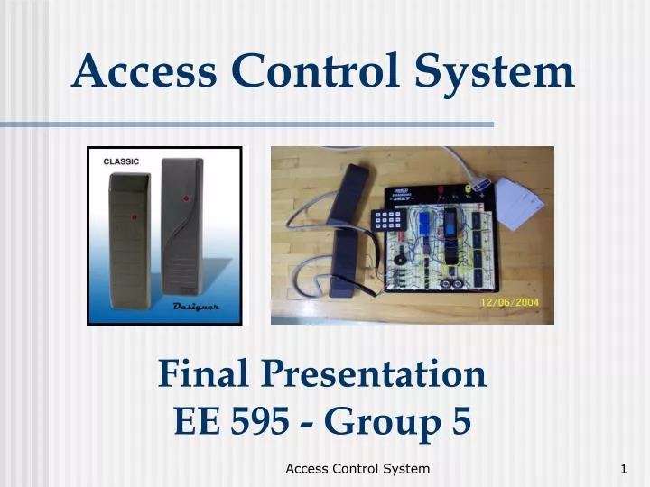
Access Control System Final PresentationEE 595 - Group 5 Access Control System
Team Member Introduction and Expertise MATT BRUNELL Software, ADC, DAC, concept-HDL JOHN BEAUCHAMP Digital Design, PLD VHDL Programming JEREMIAH BRYAR PCB Layout Design NEGEDE BERHANU Power Systems, Power Electronics WILLIAM DIETRICH ADC, DAC, concept-HDL, Law HA VO AC/DC Motors Access Control System
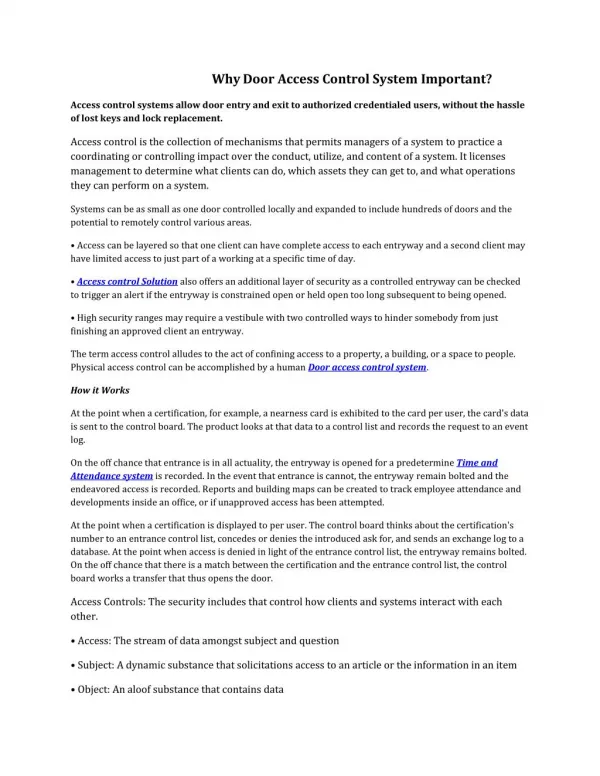
Non-Technical Description • To the user, an access control system is comprised of three elements: • A card or token (a.k.a., an identity credential) • A door reader, which indicates whether the card is valid and entry is authorized • A door or gate, which is unlocked when entry is authorized • A user presents a card to a door reader, information from the card is transmitted to the access control system, and the system determines whether the card is valid and entry is authorized. If the card passes, the system permits entry into the door. If the card fails, the door remains locked. Access Control System
Block Diagram Access Control System
Basic Operation of System Access Control System
Target Market by Geography and Demographics • Offer product in the U.S. and Canada (120 V @ 60 Hz). • Market to schools, businesses, apartment complexes • Product environment: • access points to structures Access Control System
Business Case • The electronic access control industry is estimated at $3.3 billion per year and is expected to grow at 12.8% annually. • Goal - sell 5,000 units in the first year. • Less than 1% market share initially expected. Access Control System
Business Case (cont.) • Selling Price – $300 • Material Cost – $60 • Manufacturing Cost – $90 • Development Cost – $900,000 • Return on Investment – 15 months Access Control System
Warning Labels Access Control System
Capstone Project Role: Assembly & Proto Mgr Negede Berhanu • BSEE • Expertise: Power, Power Electronics • Design Responsibilities • Block 1: Power Supply • Block 8: Relay Control Access Control System
Power Location Within Product Level Block Diagram Access Control System
High Level Description of Block • Converting 120 AC to 24 volt dc • AC-DC converting transformer 120V,60Hz to 24 V dc. • Rectifier bridge • A full waver rectifier bridge to decrease the voltage ripple. • 12V Voltage regulator • Converting 24V to 12V • 5V Voltage regulator • Converting 24V-5V • A PNP Transistor to supply power to the SRAM Access Control System
Performance Requirement • The micro processor • Max Voltage 5.5 min 4.2 • max of a current of 100mA • Super capacitor • Max voltage of 5.5 • A battery charger • Max voltage 13.8 min 11 • Max 0.5A • The relay switch • Max voltage of 12.4V , Min voltage of 11.3V at Max current of 1A Access Control System
Performance requirement cont. • Mechanical interface soldered on PCB board • In case on an accidental short it is protected by fast acting fuse Access Control System
Standard Requirement • Operating temperature range 0-400C • Testing for wide range of temperature for shipping and storage • Operating Voltage and Frequency Range • The operating voltage is 100-240 at frequencies of 50/60Hz • Market geography • North American market. • Safety • Minimal concern for electric shock or hazard. Access Control System
Standard Requirement • Allocation • Weight 70% of total weight • PCB area 422.95 mm2; 1.65% of total area • Cost 127,037;19.19% of total cost Access Control System
Block Diagram Access Control System
Theory of Operation • The ac to dc converter will change the 120V to 24V • The rectifier bridge will further smoothen out the ripple on the 24V signal • The voltage regulator will change the 24V to 12V and 5 V dc signal Access Control System
Calculating The Bias on PNP • Voltage Drop Across VBE=.7 • Using voltage divider Vb=Vs*R2/(R1+R2)=4 • Ve=VB-VBE=3.3V • IB=VB-VBE/(RB+(β+1)Re)=.5μA Access Control System
Schematic Access Control System
Simulation Result of Rectifier Bridge Access Control System
Simulation Result of 12V and 5V Voltage regulator Access Control System
12V and 5V Switching regulator High Quality Factor High Reliability A wide rang of input voltage 15-40 12V 8-40 5V Operating Temperature of -55 to 105 degrees C Soldering 2350C for 5 sec Resistors: Constructed from Metallic Film Low Cost Long lasting ability Temperature Coeff. of Resistance -55 to 155 degree C Soldering t of 2350C for 5 seconds Key Component Selection Access Control System
Production BOM Access Control System
Production BOM Cont Access Control System
Statistics & Reliability:λ, MBTF, R (t) • Total λ for the block, which is the sum of all λ is 2.422*10-6 • Total MTBF=1/ λfit 412725.5122 • The overall reliability of the block is 99.99987% Access Control System
Statistics & Reliability:Conclusion • The dominant part, transistor with 99.99927%. • The Zener diode we picked for this design has the second lowest reliability at 99.99993%. • Picking more durable transistor at cost tradeoff Access Control System
Product Sustainability Access Control System
Product Sustainability Prediction Access Control System
Obsolescence Analysis • The resistor will go obsolete by the year 2015 • Since we have 10 year period no change is recommended Access Control System
DFM Analog Access Control System
Block 8 Relay switch Access Control System
Relay Location Within Product Level Block Diagram Access Control System
High Level Description of Block • Relay switch • A normally closed relay that will conduct current through the coil in order to lock or unlock a magnetic door lock • An inverter • A digital inverter that will take a digital signal form the microprocessor that will late the relay operate as to the desired operation (lock or unlock door) Access Control System
Performance Requirement • A 12V inverter • Input voltage of 12.6-11.4V • A signal of 5V from microprocessor • The relay switch • Max voltage of 12.4V and Min voltage of 11.3V • It will draw a Max current of 1A Access Control System
Standard Requirement • Operating temperature range • The operating temperature range 0-420c • Testing for wide range of temperature for shipping and storage • Safety • Since all of the component in going to be enclosed within a the enclosure box there is a minimal concern for electric shock or hazard. • Allocation • PCB Area 206.18mm2 ; 0.81% of total PCB area • Cost 81,990.00; 12.37% of total cost Access Control System
Block Diagram Access Control System
Design Theory • Relay is an electrically operated switch. • The relay will be used to energize or de-energize the magnetic lock that will open or lock the door • The microprocessor will send a signal to the relay Access Control System
Implementation of The Design Theory • The 12V dc attached to one end of relay coil • The inverter will be powered by the 12V at the other end of the relay coil • The input signal of the inverter will be supplied by the microprocessor as high being +5 and low being 0 • Switching between 12V potential to 0V Potential the relay will operate as desired Access Control System
Production BOM Access Control System
Production BOM Cont. Access Control System
Statistics & Reliability:λ, MBTF, and Reliability • Total λ for the block, which is the sum of all λ is 5.78547*10-7 • Total MTBF=1/ λfit 1728467.679 • The overall reliability of the block is 99.99985% Access Control System
Product Sustainability Access Control System
Product Sustainability Prediction Access Control System
Obsolescence Analysis • The MOSFET will go obsolete by the year 2009 • Due to a shorter period of time we have before they go obsolete we recommend using a newer version inverter Access Control System
Capstone Project Role:Presentation Manager Bill Dietrich • BSEE • Expertise: ADC, DAC, concept-HDL, Law • Experience: UWM courses, Law • Design Responsibilities • Block 4: Input Conditioning Circuit Access Control System
Input Conditioning Circuit • Purpose • The input conditioning circuit accepts a signal from the card reader after a access card has been scanned • The circuit conditions the signal to ensure that voltages, currents, and frequencies are within permissible tolerances • The circuit digitizes the signal using a Schmidt Trigger • The circuit passes the conditioned and digitized signal through to Block 5 - PLD Parsing Circuit/PLD Programming Interface Access Control System
Physical Block Location Access Control System
Board Level Schematic Access Control System
Interfaces Signals Two 5 V analog signals (per door) Two conditioned 5 V digital signals (per door) Physical • All components in Block 4 are mounted on main PCB board. Access Control System