Download
1 / 11
110 likes | 123 Views
This overview provides a detailed description of the ideal data acquisition system (DAQ) structure for the EUDET/CALICE project. It covers the various components such as detector ASICs, front-end modules, data aggregators, off-detector receivers, and more. The text language is English.

E N D
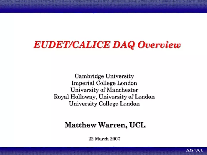
EUDET/CALICE DAQ Overview Cambridge University Imperial College London University of Manchester Royal Holloway, University of London University College London Matthew Warren, UCL 22 March 2007
Ideal DAQ Structural Overview • Detector ASICs on e.g. ECAL slab • Front-End (FE) • FE-Interface (DIF): Detector specific • FE Link/Data Aggregator (LDA): Generic • Data-link (FE to Off-Detector Receiver) • CCC-link (Clock+Control+Config to FE) • DAQ PC • Off-Detector Receiver/s (ODR) • Drives CCC-link • Data Store ASICs ASICs ASICs … DIF DIF DIF FE LDA Data-link CCC-link PC/s ODR Store EUDET/CALICE DAQ Overview
FE Structure Detail • We have 2+ types of detector to readout. • Divide the FE into a 2 part, tiered system • 1) Detector Interface module (DIF) • Detector specific interface • Includes power connectors • ‘Local’ systems (e.g. stand-alone clock) • Debug connectors • 2) Link/Data Aggregator module • (LDA) • Collects data from many ‘DIF’s • Drives data Off detector link • Receives and distributes C+C • FPGA Development board • BUT: • We would might like to read-out slabs individually first… ECAL Slab ECAL Slab HCAL Layer HCAL Layer ECAL DIF ECAL DIF HCAL DIF HCAL DIF Link/ Data Aggregator Link/ Data Aggregator C+C Fanout PC PC EUDET/CALICE DAQ Overview
Data-link (+CCC) • Use most common networking fibre-optics: • Multimode with LC connectors • SFP (mini-GBIC) interfaces • 1Gbit rate (maybe tuned to multiple of machine freq.) • Ethernet • Control up-link NOT via fibre, initially. EUDET/CALICE DAQ Overview
Off-Detector Receiver (ODR) • PCI Express Card • Virtex 4, FX100 FPGA (big!) • Hosts opto-links • 2xSFP, 2xHSSDC2 on board • Source of C+C (Control link) • Initially copper (LVDS) • Later fibre • Will use external clock and sync signals for multi-board synchronous operation EUDET/CALICE DAQ Overview
ODR(2) - Status • Firmware AND software well underway: • PCIe interface DONE • Register read/write DONE • DMA access DONE • Ethernet Interface • IN-PROGRESS • DDR2 Interface IN-PROGRESS • Linux driver DONE • Optimised Disk Store • IN-PROGRESS • Manager Software • IN-PROGRESS • Performance profiling • IN-PROGRESS • Clock and Control Uplink • NOT-STARTED Ethernet Interface DDR2 Interface Test Data Gen Arbiter Internal RAM Control/ Status Reg. Block PCIe Interface Firmware Driver Manager Software EUDET/CALICE DAQ Overview
UK Read-out work (ECAL FE) • Detector Interface (Cam, IC) • Spec + hardware • DIF to Link/Data Aggregator (Cam/Man) • Spec + hardware • Data aggregate, format (Man) • Hardware + firmware • LDA to ODR opto-link (Man, UCL) • Hardware + firmware • ODR (RHUL, UCL, Cam) • firmware • ODR to disk (RHUL) • Driver software • Local Software DAQ (RHUL) • Full blown Software DAQ (RHUL, UCL, [IC]) ECAL Slab DIF LDA Opto PC ODR Opto Driver EUDET/CALICE DAQ Overview
Clock + Control, Integration • Keep it simple! • -System synchronising signals distributed • All data tagged with common ‘timestamp’ Master In Clock Control (Train-start, Sync) Slave out Slab LDA Slab PC Slab Fanout (TLU?) ODR Config ODR Slab LDA PC Slab ODR Config Slab ODR EUDET/CALICE DAQ Overview
‘TLU’ Requirements • Lets assume 32 ‘Slabs’. • Each Slab needs: Clk; Train, (Trigger?) • But could use LDA here. At 8 slabs/LDA = 4 LDAs • With minimum 1 LDA/ODR = 4 ODRs • Each ODR needs: same + Fast Control(data) • 4 Signals Clock, Train, Trigger, Control • Fanout of 32 slabs + 4 LDA + 4 ODE =40, OR more likely 4 LDA + 4 ODR = 8. • TLU acts as Master or Slave for signalling • TLU generates signals stand-alone • We presume to use LVDS everywhere. • ?? Do we try to use the TLU for fanout, or just as a ‘machine’ interface? EUDET/CALICE DAQ Overview
Extra: • Optical Switch EUDET/CALICE DAQ Overview
Optical (Layer-1) Switching • Part of the UK CALICE is to evaluate the use of a “layer-1” switch. • 1) DAQ PC failover - Redirect data to spare unused DAQ PC on the fly • 2) “Router” - Can change data destination per bunch-train. • Regulate load by sending data directly to free resources • 3) Programmable optical patch panel (large installation) • Manufacturers offering similar products, in same price range e.g. Glimmerglass, Polatis - difficult to differentiate between them • Decided on Polatis • can switch dark fibre (i.e. not MEMS based) • Multimode fibre capable • Fastest switching time (20ms) • 16x16 array with 50μm multimode LC connectors EUDET/CALICE DAQ Overview