Download
1 / 31
320 likes | 636 Views
Recent Results of KSTAR H-modes , ELM Mitigations And TM stabilisation Yong-Su Na on behalf of the KSTAR Team. Contents. Short introduction to KSTAR H-modes L-H transition power threshold Characteristics of H-mode discharges Effect of ECRH on rotation Control of Edge Localized Modes

E N D
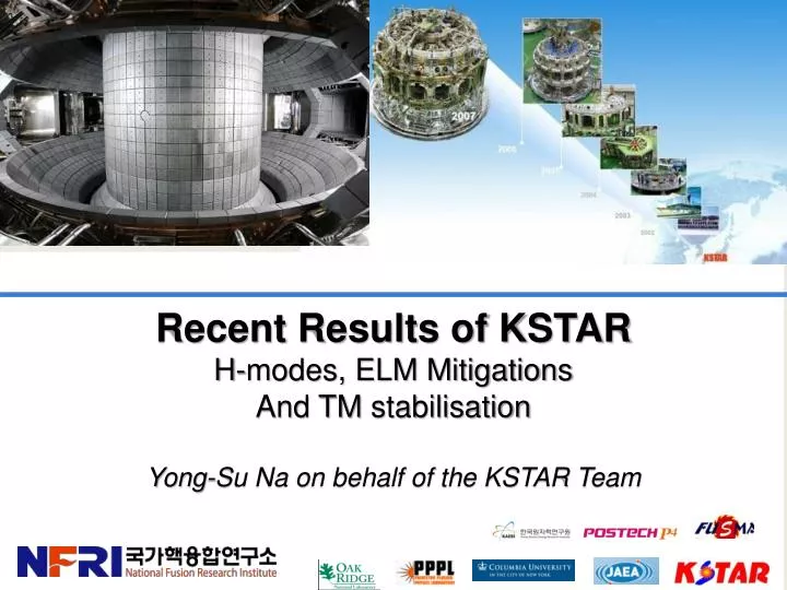
Recent Results of KSTAR H-modes, ELM Mitigations And TM stabilisation Yong-Su Na on behalf of the KSTAR Team
Contents • Short introduction to KSTAR • H-modes • L-H transition power threshold • Characteristics of H-mode discharges • Effect of ECRH on rotation • Control of Edge Localized Modes • Effect of resonant magnetic perturbation • Direct pedestal heating by ECRH • ELM mitigation by SMBI • ELM pacemaking by Vertical jog • Control of Tearing Modes 2
KSTAR Mission and Achievements KSTAR Parameters KSTAR Mission PARAMETERS Designed Achieved • To achieve the superconducting tokamak construction and operation experiences, and • To develop high performance steady-state operation physics and technologies that are essential for ITER and fusion reactor development 1.8 m 0.5 m 2.0 0.8 17.8 m3 > 0.7 C, CFC (W) DN, SN 2.0 MA 3.5 T 300 s 5.0 H, D Nb3Sn, NbTi ~ 28 MW 9 kW @4.5K Major radius, R0 Minor radius, a Elongation, Triangularity, Plasma volume Bootstrap Current, fbs PFC Materials Plasma shape Plasma current, IP Toroidal field, B0 Pulse length N Plasma fuel Superconductor Auxiliary heating /CD Cryogenic 1.8 m 0.5 m 2.0 0.8 17.8 m3 - C DN 1.0 MA 3.6 T 10 s > 1.5 H, D, He Nb3Sn, NbTi 2.0 MW 5 kW @4.5 K • Black : achieved • Red : by 2011 3
KSTAR Device for 2011 Campaign PFC Baking & Cooling 200 C NBI-1 100 keV 1.5 MW, 10 s ECH 170 GHz 0.7 MW, cw vacuumpumping ECH 84 GHz / 110 GHz 0.3 MW, 2 s ICRF 0.5MW, 1s Cryogenic helium supply 4.5 K, 600 g/s
Contents • Short introduction to KSTAR • H-modes • L-H transition power threshold • Characteristics of H-mode discharges • Effect of ECRH on rotation • Control of Edge Localized Modes • Effect of resonant magnetic perturbation • Direct pedestal heating by ECRH • ELM mitigation by SMBI • ELM pacemaking by Vertical jog • Control of Tearing Modes 5
Typical H-mode in KSTAR (2010) #4333 H-mode ELMs Da • ~30 shots achieved in 5 days • BT = 2 T, Ip~ 0.6 MA, ne ~ 2e19 m-3 • PNBI ~ 1.3 MW (80 keV, co-NBI) • PECH ~ 0.25 MW (cntr-injection to Ip) • POH ~ 0.2 MW • Double null, κ ~ 1.8, R ~ 1.8 m, a ~ 0.5 m • Boronizationwith carborane • Pthres~1.1 MW (ITER physics basis, 1999) sharp increase of edge ECE ~80% increase of βp
Roll-over of H-mode threshold power at low density Progress in ITER Physics Basis (2007)
Energy Confinement Time is in Line with Multi-Machine Database for L- and H-mode • E estimated using measured stored energy and ASTRA simulation with some assumptions • Assuming 20% (due to low density regime) fast ion fraction in the stored energy, the experimental E was estimated • L-mode: E= ~86ms, HL96=1.3 • H-mode: E=~130ms, HH98=1.1
Structure of pedestal from CES measurements Pedestal width is larger for VT Width of Ti ~2.5 cm Width of VT ~3.5 cm
ECH effect on toroidal rotation in H-mode (by XICS measurements) Core Ti drop
Rotation drop is larger for the central region CES measurements
Smaller counter torque with off-axis ECH Scan of ECH deposition layer Smaller drop of Ti
Contents • Short introduction to KSTAR • H-modes • L-H transition power threshold • Characteristics of H-mode discharges • Effect of ECRH on rotation • Control of Edge Localized Modes • Effect of resonant magnetic perturbation • Direct pedestal heating by ECRH • ELM mitigation by SMBI • ELM pacemaking by Vertical jog • Control of Tearing Modes 14
2D ECEI Observation: A Single Large ELM Crash Event Consisted of A Series of Multiple Filament Bursts • A single large ELM crash was composed of a series of multiple filament bursts • Similar observations on ion saturation currents measured from divertor probes Inner Divertor (EP 42) Outer Divertor (EP 54) KSTAR #4362 Time [sec] Courtesy by G.S. Yun (Postech) and J.G. Bak(NFRI) PRL 2011
Suppression of ELMs with n=1 Resonant magnetic perturbations • 90 phasing RMP strongly mitigated or suppressed ELMs • In JET, ELM mitigated by n=1 (Y.Liang, PRL, 2007) • Two distinctive phases observed • ELM excitation phase • ELM suppression phase • Density (~10%) pumping out initially. Then, increasing when ELM suppressed • Stored energy drop by ~8% initially. Then slightly increased or sustained when ELM suppressed • Rotation decreased (~10%) initially. Then sustained when ELM suppressed • Te/Ti changes were relatively small BT=2.0T PNBI=1.4MW Top-RMP Mid-RMP Bot-RMP
Strong locking observed instead of ELM-Suppression at relatively high edge Te 17
Direct ECH in the pedestal region Optimal edge heating at BT0 = 2.3 T
ECHnear pedestal increases fELM Shot 6313 At relatively low ν* fELM before ECH ~20~30 Hz fELMduring ECH ~40 Hz fELMafter ECH ~20~30 Hz Clear ne & VT drop Similar △WELM No clear effect of ECCD
Large ELMs are triggered by ECH at relatively high ν*
Mitigation of ELMs with Supersonic Molecular Beam Injection After SMBI injection, ELM type changed from type-I like to grassy
ELM pace-making with fast vertical jog • ~5 mm of vertical excursion trigger ELMs (~3 mm is marginal) • ELM is triggered when plasma moves away with its maximum speed
Multiple ELMs triggered with larger excursion In addition to the normal trigger, larger ELMs are triggered when the vertical position is at lower minimum
Contents • Short introduction to KSTAR • H-modes • L-H transition power threshold • Characteristics of H-mode discharges • Effect of ECRH on rotation • Control of Edge Localized Modes • Effect of resonant magnetic perturbation • Direct pedestal heating by ECRH • ELM mitigation by SMBI • ELM pacemaking by Vertical jog • Control of Tearing Modes 24
Tearing mode stabilisation experiment : m/n=2/1 tearing appears #6272 R (m) Te (keV) Vtor(km/s) Ip (kA) z (m) NBI (MW) Wtot (kJ) Hα NBI (keV) κ 170 GHz ECH (kW) βp RMP(A) 110 GHz ECH (kW) Time (s) Time (s) Time (s) Time (s)
Estimation of Island width from Mirnov coil signals MC1P03 MC1P03 FFT FFT analysis 4/2 mode 2/1 mode 2/1 mode tracking 4.6 4.5 Island width (m)
Determination of Island Location using ECE core Island width (m) island edge R (m)
Preliminary simulation of the island evolution • Te From experiment • ne, niassumed • Ti from the Weiland model • Initial width: 0.55 m • Using a2= 2 2/1 island exp. ne (1019m-3) Islandwidth (m) Simul. Te (keV) ni (1019m-3) Ti (keV) Pech (MW/m2) Time (s)
Strategy for 2012 experiments (Preliminary) • ○ Main Research Direction • Controllable H-mode (> 10 s) at ~1 MA • ITER relevant/urgent physics issues • - ELM mitigation by using RMP, SMBI, ECCD, etc • - IOS-related issues: OPEN! • Supported by Theory and modelling (ex, WCI) • ○ Hardware Priority (mission oriented) • NB(+2 MW) -> NB(3.5 MW), LH(0.5 MW), ECH(1 MW) • ICRH(1 MW) • IRC(In-vessel radial control coil) • Thomson(25ch), BES, Reflectometry, Diverter IR
Schedule in 2012(tentative) Evacuation & Wall conditioning Magnet cool-down SC magnet operation • August : Evacuation start • Sep. : Cryo-facility operation and magnet cool-down (300 K ~ 4.5 K) • Sep. : SC magnet and power supply operation • Oct. ~ Nov. : Plasma experiments • Dec. : Closing the experiments and magnet warm-up • (*) During Jan. to July, New NBI installation Plasma experiments