Download

1 / 30
300 likes | 475 Views
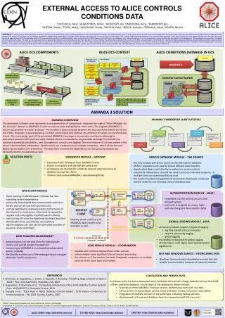
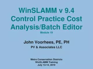
WinSLAMM v 9.4 Catchbasins/ Hydrodynamic Devices Tab 5-D. John Voorhees, PE, PH PV & Associates LLC. Using WinSLAMM to Meet TMDL, LID, and MS4 Stormwater Requirements University of Wisconsin Engineering Professional Development Pyle Center, Madison, WI April 26-27, 2011. Research Results

E N D
WinSLAMM v 9.4 Catchbasins/ Hydrodynamic Devices Tab 5-D John Voorhees, PE, PH PV & Associates LLC Using WinSLAMM to Meet TMDL, LID, and MS4 Stormwater Requirements University of Wisconsin Engineering Professional Development Pyle Center, Madison, WI April 26-27, 2011
Research Results Entering Catchbasin Data into the Model Model Output Variable Sensitivity We will cover . . .
Catchbasins . . . • Are Inlets or Manholes • Must Contain a Sump • Are not very useful if streets are also swept • Are applied as drainage controls
Parallel Collection System Manholes Inlets with Sumps Series Collection System Device Performance • Device performance a function of flow and area • Model most suited to determining device performance in parallel • Can evaluate devices in series by running separate models with increasing flows
Research Results • A New Jersey study (Pitt, et al, 1994) found average removal rates of 32% for suspended solids using catchbasins with a suitable sump. • Pitt & Shawley (1982) found cleaning catchbasin twice per year reduced total residue yields between 10% and 25%. • Pitt & Field (2004) found sediment in catchbasins were the largest particles washed from streets.
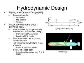
Four Components to Modeling Catchbasins • Device Density • Device Geometry • Flow and Particle Size Data • Device Cleaning Information
Access the Catchbasin or Drainage Control Menu to view the Catchbasin Device data To Access Catchbasin Device Data
Geometry Information Use average values for the drainage basin you are modeling
Inflow Bypass Data Hydrodynamic Devices Only
Inflow Bypass Data Two Options – Either User-defined Maximum Flow, or . . . Hydrodynamic Devices Only
Inflow Bypass Data Defined Flow Diversion Geometry Hydrodynamic Devices Only Lamella Plates or Tube Settlers are also an option (See Hydrodynamic Device discussion)
Catchbasin Performance Algorithms Transition from Stokes (laminar) to Newton (turbulent) Settling Rates • Settling modeled as a detention basin assuming: • Vertical sides • No storage • Particulate removal based upon particle size • Flow rate calculated using Complex Triangular Hydrograph
Catchbasin Output Catchbasin Cleaning Model Results
Drainage System Particulate Solids Yield Before Drainage System Total After Drainage System Total
Catchbasin Performance by Event Additional Output Other Output Options • Stage-outflow data • Performance by time step • Stage-inflow data
Research Results • Clark (2006) evaluated the performance of inclined plate settlers for treating stormwater solids • Greb et al (1998) evaluated the performance of a hydrodynamic device in a City of Madison maintenance yard.
To Access Hydrodynamic Device Data Double-Click on this cell to view the Hydrodynamic Device data
Defined Flow Diversion Geometry Single Chamber Device Characteristics with Maximum Flow to In-Line Sump
Defined Flow Diversion Geometry Single Chamber Device Characteristics with Inflow Geometry Bypass Data
Testing Modeling Results for Proprietary Dynamic Separators. Vortechs Stormceptor DownStream Defender
Hydrodynamic Device with Lamella Plates or Settling Tubes (v 9.4)
What are Lamella Plates? • Key Variables • Fraction of device area with plates or tubes • Average tube diameter or distance between plates • Number of plates or tubes in a vertical line Increases the effective surface area of the device by the number of times a vertical line crosses a plate or tube