Download
1 / 11
110 likes | 228 Views
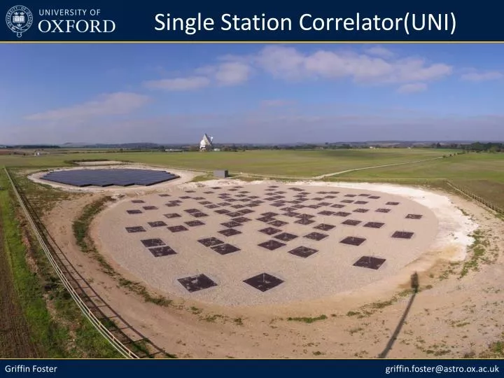
Single Station Correlator(UNI). A Widefield Imager. Science: Large field, short time resolution imaging for transient events. Daily/Weekly sky survey Engineering: Scalable FPGA based correlator design GPU image processing backend Prototype for large-N EoR arrays and SKA-Low Names:

E N D
A Widefield Imager Science: • Large field, short time resolution imaging for transient events. • Daily/Weekly sky survey Engineering: • Scalable FPGA based correlator design • GPU image processing backend • Prototype for large-N EoR arrays and SKA-Low Names: • SEPCAM (SEPnetCAMera) • LASI (LOFAR All Sky Imager) • UNI (UnNamed Imager) • …
Instrument Overview RSP GPU Imaging Node Post-Processing/Storage Server FX Correlator x24 GPU Imaging Node RSP Real Time Imager ANT 0 CH 0 FFT Cornerturn (192 Antennas x 1024 Channels) CMAC LOFAR HBA x192 ANT 192 CH 1023 FFT CMAC
Correlator Specifications • FPGA Based (UniBoard) • 96 dual-pol HBA antennas • →18624 baselines • 4 bit correlation • 15-30 MHz Bandwidth • 1024 FFT Channels • Integration times ~10 ms • Minimal modification to LOFAR station
UniBoard • Developed at ASTRON • 8 × AlteraStratix IV 40nm FPGA, type EP4SGX230KF40C2, 1288 multipliers, 1517 pins • One front node → all back nodes mesh • 14 layers • 8 × 2 DDR3 modules • 4 × 4 10GbE links in • 4 × 4 8-bit LVDS out • Estimated maximum power consumption 280 W
Correlator Design UniBoard EQ/4b Quant XAUI TX LVDS Mesh LVDS Mesh Cornerturn FN1 BN1 Mux FN2 BN2 Vacc Low Band FFT 192 antpol X Engines Vacc Xeng Out FN3 BN3 48 antpol X Engine Xeng Out Back Node FPGA 48 antpols/BN 4 BNs CLK @ 4 x Data CLK Front Node FPGA 256 Channels/FN 4 FNs CLK @ 4 x Data CLK • Daterates: • Input @ 25 MHz BW: 76.8 Gbps • Output: 141 MB per integration • Processing: • 6984 MACs @ 200 MHz: 1.4 TMACs • At 25 MHz BW complete correlation possible with 1 UniBoard
ring AP0 RCU data RCU ctrl serdes Inter board interface (IBI) AP1 BP LCU CEP AP2 Inter board interface (IBI) serdes AP3 ring RSP Interface • Current RSP Design: • Connected to adjacent RSP boards • via a 4 lane(2.5 Gbps per lane) XAUI interface • Utilizing: • Beamlets: 195312.5 Hz × 248 × 4 × 24b = 4.65 Gbps • Crosslets: 195312.5 Hz × 96 × 4 × 18b = 1.35 Gbps • Overhead: 0.025 Gbps • Total: 6.025 Gbps • Modified RSP Firmware Design: • Signal Channel correlator dropped, utilize 2 lanes for • the beam ring and 2 for UNI. Requires a passive connector • to split/combine XAUI CX-4 interface • Utilizing: • Beamlets: 195312.5 Hz × 248 × 4 × 24b = 4.65 Gbps • Overhead: 0.025 Gbps • Total: 4.675 Gbps RSP Board RCU data RCU ctrl RCU data RCU ctrl RCU data RCU ctrl CX-4 XAUI Connector
Firmware Design Options 12b Voltage samples1 • 12.5 MHz BW/ XAUI Lane • Simplest firmware modification 8b Voltage samples (quant) 1 • 18.75 MHz BW/ XAUI Lane • Maximize BW/ XAUI lane, require EQ control interface 1Limited band selection 18b Subband samples2 • 8.5 MHz BW/ XAUI Lane • Simpler firmware modification 8b Subband samples (quant) 2 • 18.75 MHz BW/ XAUI Lane • Maximize BW/ XAUI lane, require EQ control interface 2Selectable band, quantization required
Fast Transient Imaging • Channelized data is independent and is easily parallelized, GPUs offer a good solution • Short timescale images can be crude, thus traditional imaging steps can be simplified/ignored • But short timescale images must be formed faster then the integration time, the wide field of view also introduces a number of challenges. GPU phase φ0 grid/w-proj fft clean phase φ1 grid/w-proj fft clean RFI calib facet Compare Threshold FX phase φn grid/w-proj fft clean Storage Prev. Image Array Model 1 s Image Antenna Model 10 s image Sky Model Detections
Widefield Sky Survey • Longer timescale transient events • New viewable sky survey every few days • Take advantage of the fast transient pipeline by using the post RFI, calibrated data • Perform secondary integration/data compression • Follow a more traditional imaging pipeline • Analysis will focus on rare, bright, transient events which occur on timescales of minutes to days
Where we are at Firmware: • Main modules (FIR,FFT,X Engine) currently being written • LOFAR RSP modifications and passive XAUI splitter done by ASTRON UniBoard: • First round of boards(7) have been produced and shipped to institutes Imaging: • Collaborators working on GPU imaging pipeline • Widefield imaging techniques in development on prototype array in Medicina Related: • AARTFAAC (Super Terp Correlator, ASTRON/U Amsterdam)