Download
1 / 10
110 likes | 188 Views
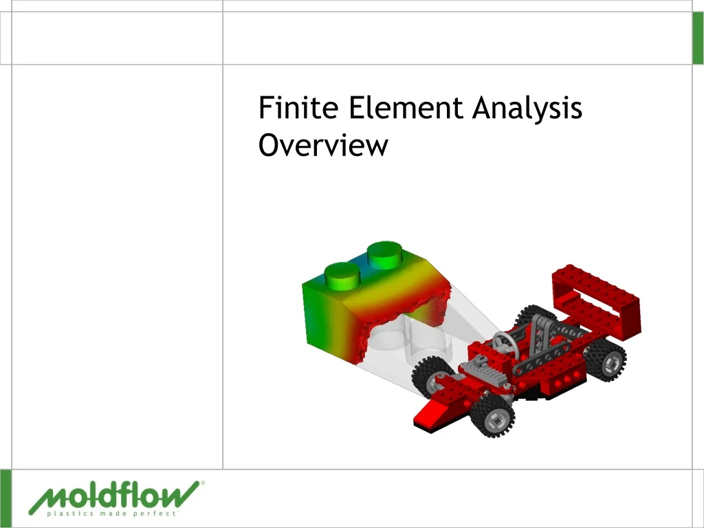
This overview discusses the mesh types used in Moldflow software, including beams, triangles, and tetrahedrals, as well as the role of nodes in determining coordinates and locations within a mesh. It highlights the advantages and disadvantages of each mesh type, emphasizing the importance of understanding their capabilities for proper application. The text covers the assumptions and considerations for midplane, fusion, and 3D mesh types in various analyses like fill, flow, gate location, and runner balance. It also touches upon the finite element analysis terminologies and their relevance in MPI simulations.

E N D
Introduction • Aim • Review the finite element meshes used by MPI • Why do it • MPI uses 3 mesh types all have • Advantage • Disadvantages • Understanding the mesh types and capability is critical for their proper application
Terminology • Mesh • Division of the physical domain into a number of sub-domains, or elements
Beam Triangle Tetrahedral Terminology • ElementA single sub-domain of a finite element mesh • Elements used in Moldflow software are • Two-node linear elements (beams) • Three-node triangular elements (shell) • Four-node tetrahedral elements (3D)
Terminology • Node • Used in a model to • Determine a coordinate position in space • Assign • An injection location • A coolant inlet • In a mesh • Nodes are the vertices of Midplane, Fusion, and 3D mesh elements and the ends of beam elements • Certain analysis results are recorded at mesh nodes
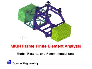
All use Beams Mesh Types Used in Moldflow All start with a CAD Model Tetrahedral 3D Volume FUSION (Dual DomainTM) Midplane
Midplane Fusion Dual Domain™ 3D Solid Mesh Types
Midplane and Fusion Mesh Assumptions • For thin-walled parts • Flowwidth should be at least 4 times the thickness • Uses generalized Hele-Shaw model • Laminar flow of generalized Newtonian fluid • Inertia and gravity effects are ignored • In plane heat conduction is negligible • Thermal convection in gapwise (thickness) direction neglected • Heat loss from edges ignored • Flow analyses includes • Fill • Flow (Fill + Pack) • Gate Location • Molding Window • Runner Balance • DOE
3D Mesh Assumptions • Designed for thick and “Chunky” geometries • Uses full 3D Navier-Stokes model • Solves at each node • Pressure • Temperature • Velocity, X, Y, Z • Considers heat conduction in all directions • Optional • Inertia • Gravity