Download
1 / 43
480 likes | 837 Views
PREAMBLE OF Electrical Machines and Automatic Control. PREAMBLE STRUCTURE HOLLISTIC FIX KEY CONCEPT KEY RESEARCH AREA KEY APPLICATION INDUSTRIAL APPLICATION RESEARCH HOW WE STUDY KEY JOBS PROJECTS ONE CAN DO TRENDS. INDEX. Introduction to the faculty.

E N D
PREAMBLE STRUCTURE • HOLLISTIC FIX • KEY CONCEPT • KEY RESEARCH AREA • KEY APPLICATION • INDUSTRIAL APPLICATION • RESEARCH • HOW WE STUDY • KEY JOBS • PROJECTS ONE CAN DO • TRENDS INDEX
Introduction to the faculty. • Abhishek Tripathi • Electrical machines lab -109 • 9307857899 • gin_mun2002@yahoo.com • 2 p.m. to 3 p.m.
PRE-REQUISITES • Basic knowledge of electrical engineering. • Kirchoff ‘s current law and voltage law. • Basic principle of transformer operation. • What is rotating magnetic field. • Synchronous machines. • Network theorems for dc sources. HOLLISTIC FIX OF E.M.A.C.
HOLLISTIC FIX………Continued • PRE REQUISTES • (1st Semester) • Phasors for resistive , capacitive and inductive loads. • Star connection. • Delta connection. • Conversion of star into delta and vice versa • Types of transformer connections. • Open circuit and short circuit test. • Introduction to machines. • Concept of rotating magnetic field. • Basic concept of laplace transformation and Fourier transformation. • Knowledge of differential equations. • Knowledge of signal and systems.
Scope of related fields. Automobile industry. Lathe machines. Robotics. Designs and layouts of a stable system. Thermal and mechanical processes. Power plant installations. Research and development of automobile industry like Maruti, Ford etc.
TREE DIAGRAM OF EMAC ELECTRICAL MACHINES AC Machines DC machines SEPERATELY EXCITED SELF EXCITED INDUCTION MACHINES SYNCHRONOUS MACHINES Series ,shunt ,compound TRANSFORMER
KEY CONCEPTS OF CONTROL SYSTEMS • Force voltage and Force current analogy. • Transfer functions. • Open and Closed loop control systems. • Signals ( step , ramp, impulse , periodic ). • Stability criteria.
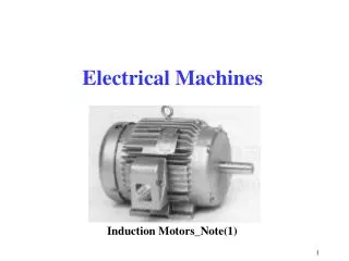
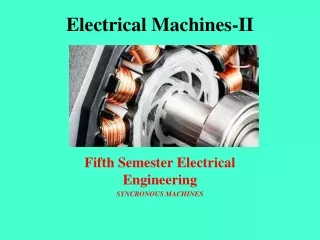
Synchronous Machines Synchronous generators or alternators are used to convert mechanical power derived from steam, gas, or hydraulic-turbine to ac electric power Synchronous generators are the primary source of electrical energy we consume today Large ac power networks rely almost exclusively on synchronous generators Synchronous motors are built in large units compare to induction motors (Induction motors are cheaper for smaller ratings) and used for constant speed industrial drives
Construction Basic parts of a synchronous generator: Rotor - dc excited winding Stator - 3-phase winding in which the ac emf is generated The manner in which the active parts of a synchronous machine are cooled determines its overall physical size and structure
d-axis Non-uniform air-gap N D»10m q-axis S S Turbine N Hydro (water) Salient-Pole Synchronous Generator • Most hydraulic turbines have to turn at low speeds (between 50 and 300 r/min) • A large number of poles are required on the rotor Hydrogenerator
d-axis q-axis Cylindrical-Rotor Synchronous Generator D»1m Turbine L » 10 m Steam Stator winding • High speed • 3600 r/minÞ2-pole • 1800 r/minÞ4-pole î Direct-conductor cooling (using hydrogen or water as coolant) î Rating up to 2000 MVA N Uniform air-gap Stator Rotor winding Rotor S Turbogenerator
Cylindrical-Rotor Synchronous Generator Stator Cylindrical rotor
Operation Principle The rotor of the generator is driven by a prime-mover A dc current is flowing in the rotor winding which produces a rotating magnetic field within the machine The rotating magnetic field induces a three-phase voltage in the stator winding of the generator
DC Motor Characteristics The performance of dc motor can be judged from its characteristic curves known as motor characteristics. Following are the three important characteristics of a dc motor:- 1.Torque and Armature current characteristics (Ta/ Ia) 2.Speed and Armature current characteristics (N/Ia) 3.Speed and Torque current characteristics (N/Ta)
Characteristics of shunt motors The field current Ish is constant since the field winding is directly connected to the supply voltage V which is assumed to be constant. Hence, the flux in a shunt motor is approximately constant. fig: connection diagram of fig-1 (Ta/ Ia) shunt motor
(N/ Ia) & (N/Ta) Characteristics fig-2 (N/ Ia) fig-3 (N/Ta)
Characteristics of series motors Note that current passing through the field winding is the same as that in the armature. If the mechanical load on the motor increases, the armature current also increases. Hence, the flux in a series motor increases with the increase in armature current and vice-versa. fig: connection diagram of series motor fig-1(Ta/ Ia)
Comparison of three motors 1.The speed regulation of a shunt motor is better than that of a series motor. However the speed regulation of a cumulative compound motor lies between shunt and series motors. (fig-1) 2.For a given armature current, the starting torque of a series motor is more than that of a shunt motor. However, the starting torque of a cumulative compound motor lies between series and shunt motors. (fig-2) 3.Both shunt and cumulative compound motors have definite no load speed. However, a series motor has dangerously high speed at no load. (fig-3)
Comparison of three motors fig-1 (N/Ia) fig-2 (Ta/Ia)
Characteristics of cumulative compound motors The following fig shows the connection diagram of cumulative compound motor. Each pole carries a series as well as shunt field winding; the series field aiding the shunt field. fig: connection diagram fig-1 Ta/Ia
What is Control and Control System? • Control is the process of causing a system variable to conform to some desired value. • Manual control Automatic control (involving machines only—the topic in this course). • A Control system is an interconnection of components forming a system configuration that will provide a desired system response. • Types of control – Open-loop control – Closed-loop (feedback) control * Indian Institute of Information Technology - Allahabad
What is Control? Manual versus Automatic Control • Control is the process of causing a system variable (e.temperature, position) to conform to some desired value or trajectory, called reference value or trajectory • Example: driving a car implies controlling the vehicle to follow the desired path and arrive safely at a planned destination • If you drive the car yourself, you are performing a manual control of the car. If you design a machine (or use a computer) to do it, then you build an automatic control system Indian Institute of Information Technology - Allahabad
Open-loop/Closed-loop Systems(Cont’d) • Open Loop • Closed-Loop (Feedback system) Indian Institute of Information Technology - Allahabad
Example 1: Car and Driver • Objective function: To control the direction and speed of the car • Outputs: actual direction and speed of the car • Control inputs: road markings and speed signs • Disturbances: road surface and grade, wind, obstacles • Possible subsystems: the car alone, power steering system, braking system, . . . Indian Institute of Information Technology - Allahabad
Example 1: Car and Driver Functional Block Diagram and Time Responses Indian Institute of Information Technology - Allahabad
Example 2: Antenna Positioning Control System • Original system: the antenna with electric motor drive systems. • Control objective: To point the antenna in a desired reference direction. • Control inputs: Drive motor voltages. • Outputs: The elevation and azimuth of the antenna. • Disturbances: Wind, rain, snow. Indian Institute of Information Technology - Allahabad
Example 2: Antenna Positioning Control System • Original system: the antenna with electric motor drive systems. • Control objective: To point the antenna in a desired reference direction. • Control inputs: Drive motor voltages. • Outputs: The elevation and azimuth of the antenna. • Disturbances: Wind, rain, snow. Indian Institute of Information Technology - Allahabad
Control System Components • System, plant or process (to be controlled) • Actuators (converts the control signal to a power signal) • Sensors (provides measurement of the system output) • Reference input (represents the desired output) • Error detection (forms the control error) • Controller (operates on the control error to form the control signal, sometimes called compensators) Indian Institute of Information Technology - Allahabad
Basic Integrants in Control Systems Analysis – Given a system, to analyze the system’s 1. Stability 2. Dynamic characteristics 3. Steady-state characteristics • Design (Synthesis) – Design a new system or compensate (modify) an existing system for 1. Stability guarantee 2. Good dynamic performance 3. Satisfactory steady-state performance • Indian Institute of Information Technology - Allahabad
KEY RESEARCH AREA OF ELECTRICAL MACHINES AND CONTROL SYSTEM. Exhaust Gas Energy Recovery. According to a first aspect of the present invention there is provided an exhaust gas thermal energy recovery system of a hybrid electric vehicle including a catalytic converter, a cooling device, a resonance tube, a control valve means and an electric generating device. The catalytic converter is disposed in an exhaust system of an engine of the hybrid electric vehicle. The cooling device cools a part of the catalytic converter. In the resonance tube, one end portion of the resonance tube is connected with an exhaust gas upstream side of the catalytic converter in the exhaust system and the other end portion of the resonance tube is connected with an exhaust gas downstream side of the catalytic converter. The control valve means is provided near the both end portions of the resonance tube so that the control valve means can form a loop path by using the resonance tube and the catalytic converter. The electric generating device is connected with the resonance tube to generate electric power according to reaction of air pressure vibration generated due to a temperature gradient in the catalytic converter. After the engine is stopped, the control valve means forms the loop path and the cooling device cools down the part of the catalytic converter to generate the temperature gradient.
EMPLOYMENT OPPORTUNITIES Electronics Corporation of India Limited. www.ecil.co.in Bharat Electronics Limited. www.bel-india.com Hindustan Aeronautics Limited. www.hal-india.com Defense Research & Development Organization. www.drdo.org Indian railways. www.rrbald.nic.in
JOBS WEBSITES… www.jobisjob.com www.careerdice.com electricalengineeringtour.blogspot.com jobview.monster.ca careercenter.aiaa.org hotjobs.yahoo.com freshersworld.com monster.com naukri.com timesjobs.com
PROJECTS….. Auto hammer striker Auto side stand indicator and center stand AUTOMATIC LUBRICATING MACHINE AUTOMATIC DISC PARKING SYSTEM AUTOMATIC DRILLING AND TAPPING MACHINE Automatic gear changer