Download
1 / 5
0 likes | 36 Views
This document describes adjustment of Grid Control M210 or M310 flow switch. This<br>document could help you restore the operation of the installed flow switch if you<br>accidentally disturbed the setting by moving the settings screws out of range.

E N D
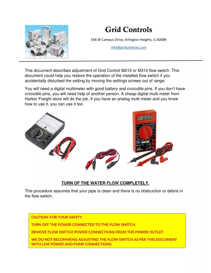
Grid Controls 546 W Campus Drive, Arlington Heights, IL 60089 info@gridcontrols.com This document describes adjustment of Grid Control M210 or M310 flow switch. This document could help you restore the operation of the installed flow switch if you accidentally disturbed the setting by moving the settings screws out of range. You will need a digital multimeter with good battery and crocodile pins. If you don’t have crocodile pins, you will need help of another person. A cheap digital multi meter from Harbor Freight store will do the job. If you have an analog multi meter and you know how to use it, you can use it too. TURN OF THE WATER FLOW COMPLETELY. This procedure assumes that your pipe is clean and there is no obstruction or debris in the flow switch. CAUTION: FOR YOUR SAFETY. TURN OFF THE POWER CONNECTED TO THE FLOW SWITCH. REMOVE FLOW SWITCH POWER CONNECTIONS FROM THE POWEROUTLET. WE DO NOT RECOMMEND ADJUSTING THE FLOW SWITCH AS PER THIS DOCUMENT WITH LIVE POWER AND PUMP CONNECTIONS.
STEP 1: Connect The meter as shown in the photo below. Select 20K or 200K or 2000K range on the digital multi meter. Before connecting crocodile pins to the flow switch, connect them together and make sure your meter reads 00.0 (or 0.00). Open the crocodile pins and your meter should read 1 as shown below. Once you check the meter, connect the two crocodile pins to the COM and NC pins of the microswitch as shown in the photo. Top two pins of one microswitch out of two microswitch in 220V model. Top two pins of the microswitch in single microswitch models.
STEP 2: After connecting the meter to the flow switch, please note down what meter is showing. It must show either “1” or “00.0”. If the meter is showing 00.0, you can skip this step and move to STEP 3. Using “+” screw driver (non-magnetic is better), turn the screw clockwise looking from the top (or in), quarter turn at a time (shown by the blue arrow in the photo). After every quarter turn, check the meter. If it reads “00.0” stop. Take the screw driver off. ➢Using finger, push the flapper down. ➢ The meter should now read “1”. ➢Release the flapper. ➢ If the meter comes back to “00.0”, go to STEP 3. If the meter still shows “1”, using screwdriver, turn the settings screw clockwise looking from the top. Remember, quarter turn at a time. Until it reads “00.0”. Repeat the flapper push down and release process as describe earlier. Once you established that, ➢ The meter shows “1” when the flapper is pushed down by finger or screwdriver ➢ The meter shows “00.0” when the flapper is released. Normally the meter should show as below, You can move to STEP 3.
STEP 3: In STEP 2, we established that the flow switch stays ON. That is the minimum condition. Now we must come to a point where we make the switch operational again. ➢ Using same “+” screwdriver, rotate the settings screw counterclockwise (anti clock direction or out). ➢ Remember, quarter turn at a time. ➢ After every quarter turn, take your screwdriver away and check the meter. ➢ Is your meter reading “1” now? If “NO” then repeat the quarter turn out process until you see “1” on your meter’s display. STEP 4: Now using your finger (or screwdriver), perform following steps, ➢Push the flapper up ➢ The meter should read “00.0” ➢Release the flapper ➢ If your meter reads “00.0”, go back and restart the STEP 3. ➢ If your meter reads “1”, repeat STEP 4 for 3 more times and see your results are consistent. ➢ To add more safety to the settings, move the settings screw half turn out (anti clock direction or counterclockwise as shown by the blue arrow on this page.)
STEP 5: Keeping meter connected, turn on the flow. The meter should read “00.0” when there is enough flow through the switch. Approximately 1.2 GPM should turn on the switch. If switch still reads “1”, you have two options, - Check the leakage between water pump and flow switch. If you have water running somewhere else and not going through the flow switch, the switch will not turn on. - The water flow rate is low, using 5-gallon bucket, make sure that it fills up in 4 minutes. If it takes more time, the water flow rate is low, and the switch will not turn on. Many times, one faucet does not generate enough water flow to fill up 5-gallon bucket in 4 minutes. STEP 6: Once you established that the meter is reading “00.0” when the water is flowing and the meter is reading “1” when the water is turned off, you can proceed to connect your wiring back to the flow switch. Check your wiring before turning on the power.