Download

1 / 22
220 likes | 236 Views
ECE Final presentation. Adrienne Preeya Aisling Shea. Adrienne Coulter. Preeya D ’ Mello. Shea Cassidy (& Kangaroo Friend). Aisling Casey. Sensor characterization. Sonar Sensor Uses “ echoes ” of sound waves to locate an object ’ s distance

E N D
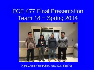
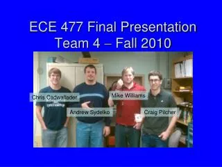
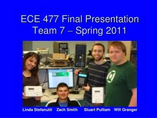
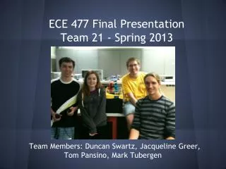
ECE Final presentation Adrienne PreeyaAisling Shea
Adrienne Coulter Preeya D’Mello Shea Cassidy (& Kangaroo Friend) Aisling Casey
Sensor characterization • Sonar Sensor • Uses “echoes” of sound waves to locate an object’s distance • The closer the distance, the larger the reading on the handy board
Sonar Sensor Code void main() { int range=0; printf("\n Sensor Sample Program"); while(!start_button()); // Press Start Button while(1) // Continue infinitely { sleep(0.5); range = sonar(); printf("\nOutput is %d", range); } }
Sensor characterization • Light Sensor • Records the darkness/lightness of on object or scale, and converts them into readings • Complete black was 100% on the scale, while complete white was 0% • Low values indicate bright light, while larger values indicate low light
Light Sensor Code void main() { int sensor1=0; printf("\n Light Sensor Sample"); while(!start_button()); // Press Start Button while(1) // Continue infinitely { sleep(0.5); sensor1=analog(4); // Reads the signal coming from analog port 4. printf ("\n LightSensor%d", sensor1); } }
Circuits • To begin our work with circuits, we calculated the theoretical values of voltage drops, current and resistance in various prompted circuits • Ohm’s Law: V=IR • We distinguished parallel and series circuits • Resistance in series: Req= R1 + R2 • Resistance in parallel:1/Req=1/R1+1/R2
DC Circuits • Materials for DC: breadboard, resistors, a diode, a DC Power Supply, and a multimeter. • The breadboard was the main component of the circuit. • Resistors and diodes were used to build parallel and series circuits. • Once the circuit was built we hooked up a DC Power Supply to the bread board using wires. This sent current throughout the bread board. • We used wires to connect a multimeter to our breadboard. The multimeter measured the voltage across each resistor, current through the circuit and resistance.
AC Circuits • Materials for AC: BNC cable, a banana, 2 mini-grabbers, a function generator for AC current and an oscilloscope. • We connected the circuit to the function generator for an AC power source supply, and analyzed the graph of the current on the oscilloscope. • We determined the frequency and amplitude (voltage) for the various circuits.
Instrumentation DC Power Supply Multimeter Supplies power to a circuit. Between -25V and 25V Measures current, voltage and resistance through a circuit
Instrumentation Oscilloscope: measures and graph how voltage changes with time
Multisim • In this lab we further explored the mechanisms of circuitry. We built virtual circuits that we could test without having to physically build them. We used a virtual multimeter to measure the voltage and current through each circuit. We then used a virtual oscilliscope to see how the voltage changed over the course of time.
AM Radio Lab • Materials: printed circuit board, resistors, capacitors, semiconductors, & other parts • We soldered in order to connect the wires in the circuit. This required a soldering iron, solder, and dexterity. • We picked up a news station and a latin music station.
Arduino Lab Week 1 • In this lab, we built a circuit and became familiar Arduino to program an LED to light up with varying levels of brightness and colors.
Led Code intREDPin = 3; // RED pin of the LED to PWM pin 3 intGREENPin = 5; // GREEN pin of the LED to PWM pin 5 intBLUEPin = 6; // BLUE pin of the LED to PWM pin 6 int brightness = 0; // LED brightness int increment = 5; // brightness increment (changing this will change the smoothness of transitions) void setup() { pinMode(REDPin, OUTPUT); pinMode(GREENPin, OUTPUT); pinMode(BLUEPin, OUTPUT); //blue pin mode definition } void loop() { brightness = brightness + increment; // increment brightness for next loop iteration if (brightness <= 0 || brightness >= 255) // reverse the direction of the fading { increment = -increment; } brightness = constrain(brightness, 0, 255); //function which limits a value to a range analogWrite(REDPin, brightness); //analogWrite(GREENPin, brightness); analogWrite(BLUEPin, brightness); //blue pin value refresh delay(2); // wait for 20 milliseconds to see the dimming effect }
Arduino Lab Week 2 • We used our programming skills from the previous part to program a motor to rotate based on its light sensitivity.
Motor code int servoPin = 4; //variable to store the servo pin number int pulse = 700; //variable to store the pulse duration void setup() { pinMode(servoPin, OUTPUT); //set the servo pin as an output Serial.begin(9600); //set serial data transfer rate } void loop() { digitalWrite(servoPin, HIGH); //send 5V to the servo delayMicroseconds(pulse); //for pulse microseconds digitalWrite(servoPin, LOW); //send 0V to the servo delay(20); //for 20 milliseconds }
Worked as a team to execute these projects • Consulted with one another when faced with a complication or problem ConclusionECE 1020 Section 30 Aisling Casey Shea Cassidy Adrienne Coulter Preeya D’Mello